MEAM.Design - SolidWorks - The Design Library
The design library and underlying toolbox include a large number of pre-defined components, including fasteners, gears, bearings, washers, and structural members which can be quickly inserted into assemblies.
Selecting a stock component from the toolbox
The toolbox lives within the Design Library, which can be accessed by clicking on the library icon to the right of the main window:
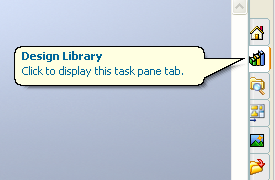
This will then show a pop-out menu with a number of options:
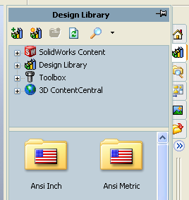
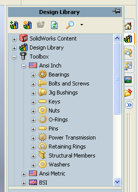
Expanding the Toolbox by clicking on its plus icon will show you some of the many standards that are used for defining stock components. For the most part, the things you'll need should be available in the ANSI (American National Standards Institute) Inch and/or Metric sections. Here we see the options under ANSI Inch:
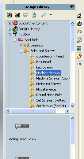
Now, you'll need to pick the type of component (for instance 'Bolts and Screws') and then select the specific style you're looking for (perhaps 'Machine Screws'). Note - this is where things can get a bit overwhelming! Once you've picked the style, you should see a number of options appear in the lower menu box, complete with small views of the corresponding 3d models.
Once you find the component you're looking for, you need to drag and drop it into your main window (note - the scale will most certainly be wrong, and you needn't worry about position or orientation at this point), then progress to the next step.
Note: If you try to insert a toolbox component into a part file, it will ask if you're trying to make a derived part - doing so would bring the toolbox component in as a solid reference feature that is non-editable within the part - this is usually not what you want.
Specifying the component parameters
Once you drag-and-drop a library component into your assembly, the left-panel will display the various properties for the component. For instance, if we'd chosen the Round-Head Screw option from the ANSI Inch - Machine Screw category, we'd see the following
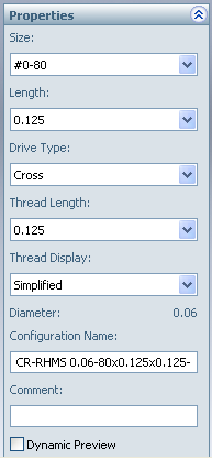
To see the actual size of the fastener, you'll need to turn on the Dynamic Preview (the checkbox is usually the last item in the Properties box), and there are often multiple options for how details are shown. For threaded fasteners, there are three options - Simplified (nothing), Cosmetic (gradients that kinda look like threads), Schematic (3d ridges that look like threads but don't actually spiral). You should find most common sizes and configurations for these stock parts available in the drop-down lists, but if you have a non-standard part, just select the closest match for now.
Placing the component
Once you've finished setting the parameters, click one of the green check marks to accept and apply the settings. You'll see that SolidWorks automatically assumes that you're going to want to place another of the same component - if you do, just click on the screen to drop another instance, or click the red X (or hit ESC) to stop adding instances.
You should now see the component listed in the model tree. You can now apply standard mates to constrain the component to your other part(s).
Editing the component parameters after placement
Editing toolbox components is different from regular parts. If you want to change the properties of the toolbox component (e.g. change the length of a screw), you need to right click on the part (either in the model tree or in the main window) and select Edit Toolbox Definition, at which point you should see the same options as were available in the above Specification step.
If you select either Edit Part or Open Part, you'll receive warning messages that you're trying to edit a read-only part since the toolbox model actually lives deep within the SolidWorks file structure. See below for the easiest way to get local copies of the toolbox models that you can then modify.
Saving your toolbox components with your assembly
To ensure that you'll have your fasteners wherever you open up your assembly (not all computers in all labs have the same toolboxes!), you should use the Pack-and-Go to save off a copy of any design library elements along with your assembly and part files. This can also be used to get a local copy of a toolbox components for editing. The files that are saved are specific to the type of element, but retain the adjustability of toolbox components (i.e. - you can still change properties such as thread pitch, length, etc. as described above).
Editing toolbox components
If you need to modify a standard component beyond the possibilities given in the properties, you can always save a local copy (see Saving, above) and open it for editing. It's worth noting that this is often challenging, as many of the sketch/feature dimensions are driven from the properties and may not be easy to adjust.