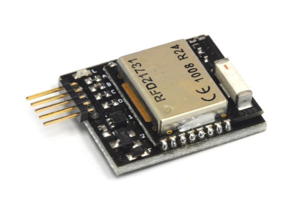
MEAM.Design - MAEVARM - mRF Wireless Module

Overview
Operating on the mBUS peripheral subsystem, the mRF module includes a custom-programmed Nordic nRF24LE1 2.4GHz wireless transceiver assembled by RF Digital along with a 3.3V regulator and level shifters for bi-directional communication with the m2 microcontroller.
Setup
To use the mRF module, you will first need to download and include support for the mBUS subsystem, which can be done from here. You will then need to download the following mRF-specific support files:
Be sure to include the C file in your project:
- For Windows OS users, if you're using Option 1, you will then need to right-click on the Source Files folder, and select Add Existing Source File(s)..., then select the m_rf.c file, and if you're using Option 2, place m_rf.c in src/.
- For Mac and Linux users, if you're using Option 1, edit your Makefile to add "m_rf.o" after "main.o" on the OBJECTS line, and if you're using Option 2, place m_rf.c in src/.
Also, place the H file next to your main file for Option 1 or place the H file in inc/ for Option 2, and include m_rf.h in your main routine.
Functions
The mRF wireless module is software configurable to operate on one of 32 distinct wireless channels within the 2.4GHz spectrum, and within each channel it can communicate with up to 256 different devices. Provided you've included m_rf.h, you will have access to three custom functions, as described below:
First, configure the mRF module to listen to a desired RXaddress (0x00 to 0xFF) over a wireless channel (1-32, TX/RX must match) with a specified packet_length (1-32, TX/RX must match):
m_rf_open(channel, RXadddress, packet_length)
Whenever the mRF module receives a message on it's channel/address, it will pull the D2 line low, which will generate an interrupt to the INT2_vect handler. The following function will extract packet_length bytes of data from the mRF module into buffer.
m_rf_read(buffer, packet_length)
The following function will send a buffer of packet_length (1-32, TX/RX must match) bytes to a specified TXaddress (0x00 to 0xFF).
m_rf_send(TXaddress, buffer, packet_length)
Hardware Confimation
First, make sure the mRF module is receiving power via the green LED onboard the module. If this isn't illuminated, use a multimeter to check for 5V coming into the board via the middle pin of the mBUS connector.
If it has power but you are doubting whether your hardware is functioning properly, download the following zip file, which contains a pair of pre-compiled hex files that you will need to load onto two separate m2 modules with corresponding mRF modules.
You must upload ping.hex to one module and pong.hex to the other. These routines operate on wireless channel 12 with addresses of 0xA3 and 0xD9. When running successfully, you will see the green LED on the m2 bouncing back and forth between modules. If transmission is unsuccessful, the red LED will illuminate.