MEAM.Design - MAEVARM - mPort GPIO 16 Pin Port Expansion Board
Overview
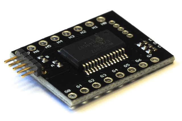
Operating on the mBUS peripheral subsystem, the mPort module includes an MCP23017 16 pin GPIO port expansion IC. The board provides 16 additional digital I/O pins that can be useful for wiring up LED segment displays. You can attach up to 8 mPort devices to a single MEAVARM, giving 128 additional I/O pins. To do so, you must ensure that the address of each board is unique. This can be done by applying solder to the pads on the bottom of the board. When looking at this side of the board oriented so that the pads are at the bottom, the left-most pin can be viewed as the most significant "bit" (i.e. soldering this pad will change the address of the board from 0x20 to 0x24).
The mPort can be connected to the m2 with the 5-pin end connector, and other boards can be connected through the mPort through the optional 5-pin female connector on the opposite side.
Setup
To use the mPort module, you will first need to download and include support for the mBUS subsystem, which can be done from here. You will then need to download the following mIMU-specific support files:
Be sure to include the C file in your project:
- For Windows OS users, if you're using Option 1, you will then need to right-click on the Source Files folder, and select Add Existing Source File(s)..., then select the m_port.c file, and if you're using Option 2, place m_port.c in src/.
- For Mac and Linux users, if you're using Option 1, edit your Makefile to add "m_port.o" after "main.o" on the OBJECTS line, and if you're using Option 2, place m_port.c in src/.
Also, place the H file next to your main file for Option 1 or place the H file in inc/ for Option 2, and include m_port.h in your main routine.
Functions
A set of routines have been developed to easily configure and use the device. All functions will return 1 if successful, or 0 if there was a communication error.
m_port_init(unsigned char address)
Where address is the address of the device matching the state of the pads (0x20 is the base address if you haven't bridged any of the pads).
Once initialized, you can write or clear individual pins and request the state of a pin by interactions with one of four registers on the mPort: DDRG and DDRH are data-direction registers for the two ports, while PORTG and PORTH are the actual port pins. To configure a pin in PORTG/H as an output, you will need to set it's corresponding bit high in the DDRG/H register (and visa-versa for inputs).
unsigned char = m_port_set(unsigned char address, unsigned char register, unsigned char bit)
unsigned char = m_port_clear(unsigned char address, unsigned char register, unsigned char bit)
To read the state of a port pin, you will use a function very similar to the general MAEVARM check(register, pin) function. This function will check the state of a single bit (0-7) in a register (PORTG or PORTH). Recall that to use the pin as an input, you must first call m_port_clear() on the corresponding pin in the DDRH or DDRG register!
unsigned char = m_port_check(unsigned char address, unsigned char register, unsigned char bit)
Important Notes (Please Read!)