MEAM.Design - SolidWorks - Flexible Objects
(License server is down, so I can't complete this now - drat!)
There are some variants on this theme, but the basic idea is to drive a dimension (or dimensions) by the distance (or angle) between other parts in the assembly.
To have SolidWorks rebuild the flexible component while moving other parts, you need to define a dimension between the moving parts. This must be done within the flexible part, but referencing the assembly geometry.
Getting started
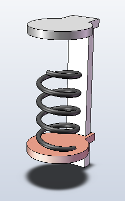
For instance, to the left we see an assembly containing a pad, a plunger, and a spring, which we want to place between the two. As shown, the spring has been mated to the bottom pad, but we will not mate it with the plunger, as this would fully constrain the part. Note - this spring was brought in as a pre-existing model, but all of this could be done as an part created within the assembly (Insert > Component > New Part...).
Defining the driving dimension
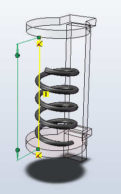
Now, we need to define the dimension between the assembly components. This must be done within the flexible part model, not at the assembly level! For the spring model we're using here, we can right-click on the model, and select Edit Part. Now, we are going to add in a new sketch on a plane that will allow us to capture the flexible dimension. To the left, you can see that we're editing the component, and have created a sketch with a single line connect the pad and the plunger. This line should be fully defined by the assembly parts. We then add a smart dimension to this line. SolidWorks should warn that the dimension over-constrains the model and prompt you to make it driven - this is what you want.
Now, you may want to rename the sketch (double-click on the name in the model tree) you just created to make it easier to reference later. For the model we're using, we renamed the sketch to assem_distance. This will also help you to remember what you've done if you come back to this part later.
You may also want to hide this sketch.
Adding the equation
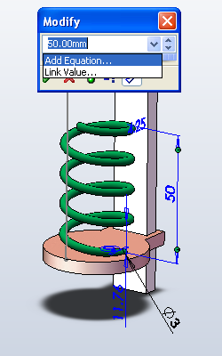
Now, still in Edit Component mode, we need to add an equation to make the length of the flexible component (our spring) match the length of the line. We'll do this by double-clicking on the spring, then double-clicking on the spring length (note - this only works if the height was one of the parameters for the spring - the pitch/revolutions method will not work). To the left you can see that we've double-clicked on the spring height dimension, and are selecting Add Equation... from the drop-down menu.
We're going to set this dimension to be equal to D1@assem_distance, though you'd want to replace that with whatever you called your sketch. D1 corresponds to the first dimension in the sketch, and there should only be one anyway, so this is a good guess.
And below we have a short animation created by moving the plunger.
(:quicktime Attach:sw_flex_7.mov height=410 width=244 controller=true:)
---
Teuvo
How to make other flexible object by defining set of constraints
1. You need to have assembly, where you have at least one movable object, for example arm.
In the following example simple wire is made flexible. Following method can be applied to any geometry with proper constraints.
2. Now that you have your assembly open, push Insert > Component > New Part.... This will add new part to your assembly, and you need to draw in it assembly mode, which can be tricky sometimes. Now SolidWorks should ask you to save your new part you're adding to your assembly. After you've saved it, you'll return to the assembly screen and you have to select a plane to draw on to.
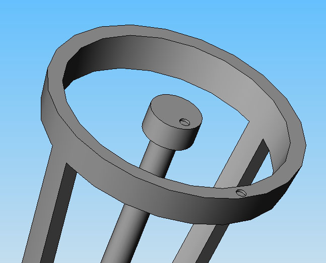
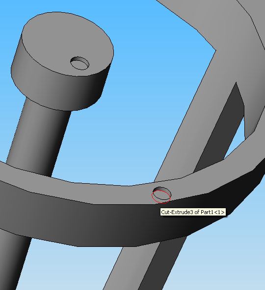
The way I like to do this, is that I first sketch the profile I want to sweep, in this case I select the bottom of this small circular cut to be my new plane, see next picture.
3. Sketch wanted profile, in this case circle.
4. Finish your sketch and then draw a spline, like in this example, between the places you want your flexible part to be.
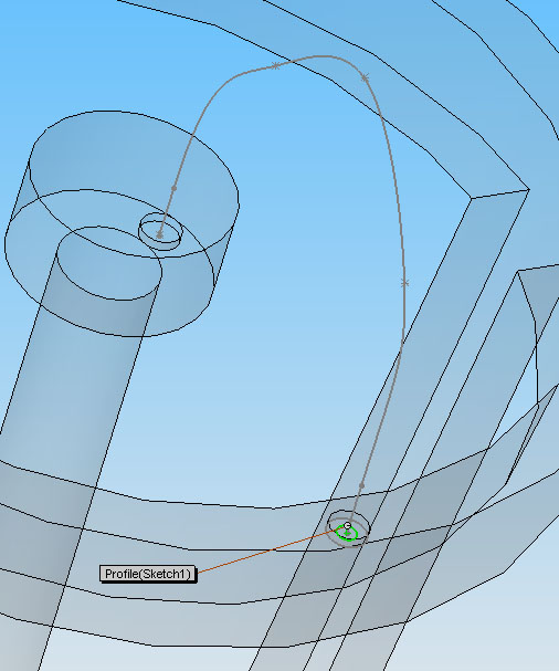
5. Do Swept Boss/Base using your profile and path.
Now you should have something similar to the next picture between your 2 parts.
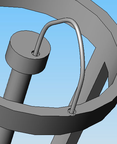
Now rotate, move your part up or down, whatever you want to do, and the hit the Rebuild button ("traffic light" button) and your sweep is rebuilt.
NOTE: Moving your part has some limitation, easiest way to figure how much you can move your part is simply just to test.
Now we can make a nice animation out of this - and the part we just made seems to be flexible!
Push refresh to see the video again
(:quicktime Attach:Assem1.avi height=410 width=244 controller=true:)