MEAM.Design - SolidWorks - Lofts
You can create either additive (boss/base) or subtractive (cuts) lofts from two or more profiles (we generally use sketches or existing faces). You will have many options for controlling the shape of the loft between the profiles, as will be explained below.
Getting started
You’ll need at least two profiles to start lofting.
Clicking on the Lofted Boss/Base button (if you want to create a lofted cut, you’ll need to select that from the Insert menu), brings up the property manager show to the right.

Selecting Profiles
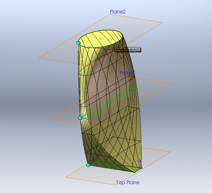
We need to start by selecting the profiles that will define the loft. You can select sketches, faces, edges, or points. Once you select more than one profile, you should see a preview of your loft, though it’s likely not quite what you want (we’ll get there!).
To change the order of a profile in your loft, highlight it in the selection box and click the up or down arrows.
Synchronizing Profiles
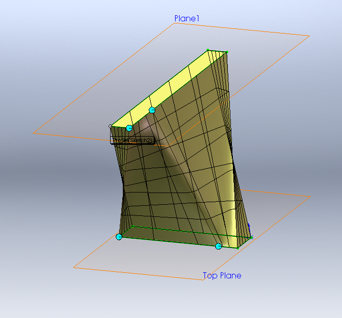
SolidWorks needs to know what points to connect between the two (or more) profiles. As you can see in the two examples below, the resulting geometry can change drastically as you modify the connections (note the locations of the blue markers in the two images) - this process is called "synchronization".
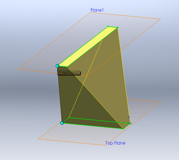
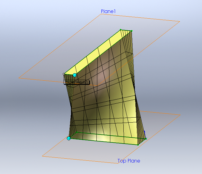
SolidWorks will start by defining a simple set of vectors, most likely between vertices on each sketch. For simple profiles like those shown above, you can change the synchronization by selecting one of the connector points and dragging it toward a different vertex (it will snap there once you move far enough).
To increase the level of synchronization control between the two sections, you can create additional sets of connectors by right-clicking on one of the sketches and selecting add connectors. Once you've done this, you can actually drag any of the connectors along the sketch/edge (i.e. - they don't need to lock on to vertices).
Modifying the Start/End Constraints
With two profiles, you have a number of options for controlling how the loft behaves near the endpoints. If both profiles are sketches, your options include None (the default), Normal to Profile where the loft faces will start/end perpendicular to the sketch, and Direction Vector, where you can specify a vector to define the normal direction. You can control the strength of tangency control by dragging the purple arrow. If one or more of the profiles is existing geometry, you will also have options to set the start/end to be Tangent to Face or Curvature to Face, which both work to smooth the transition into the new feature.
With three or more profiles, the Default option becomes active, which is said to approximate a parabola through the profiles.
