MEAM.Design - SolidWorks - Drawings / Working with Dimensions
There are a number of ways to show dimensions in your drawing:
Inserting Dimensions Defined in Your Part
The easiest (and most versatile) method is to bring forward the dimensions that you defined when you created your part. The big advantage here is that the dimensions are associative to the part itself, and changes made in the drawing will carry back into the model.
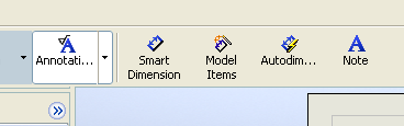
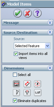
To start this process, select the big Annotation button, then click the Model Items button, which will bring up the Property Manager shown to the right.
Under Source/Destination, you can have it import either just the dimensions associated with a selected feature (default), or for the entire model, and you can specify whether to place dimensions in all views (default) or select which view(s) to use.
If you choose to use the selected feature option, you then need to click on the features in the drawing and it will bring in any dimensions associated with said feature.
If you choose the entire model option, you can simply click the green check mark and it will bring forward everything it finds.
You'll notice that these dimensions (should) show up in black, which means that they are editable and will modify the model accordingly.
Autodimension
This is not a recommended method, and will therefore not be covered here. So sorry.
Smart Dimension
While all pertinent geometry should be dimensioned in the model file (and therefore accessible through Model Items), if you need to add additional dimensions, you can use the Smart Dimension tool under the Annotations section. You'll see that these dimensions will show up in grey, which indicates that they are driven from the geometry and therefore are not editable.
Dimension Placement
Dimensions should never be placed over top of geometry, and when possible the leader lines on the ends of the dimension should not contact the part lines (you can click and drag the end of the leader lines to move them off the part if necessary).
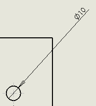
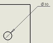
Orienting text
If you want to change the orientation of the dimension text for circles, arcs, and chamfers (the default may have the text oriented along the leader line, which can be visually disturbing), you can go into Tools > Options..., switch the Document Properties tab, select Dimensions, click the Leaders... button, check the box next to Override standard's leader display, and change the settings accordingly.