Datums
Datums are used to create reference geometry, or geometries which are not physically present in the part, but off which it is convenient to base physical part geometries. They can be found on the Feature Operation Toolbar or by Insert->Datum/Point->select a datum.
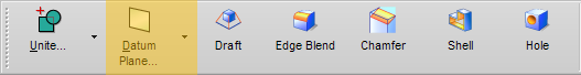
Datums on the Feature Operation Toolbar
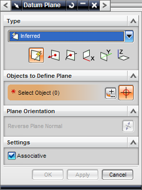
Datum Plane menu with Inferred selected.
Datum Plane
Type
There are various modes of Datum Plane definition, most of which are quite self-explanatory.
Inferred - Infers a convenient plane based on selected objects.
At Angle - Creates a plane by selecting a 0-degree position plane and rotating it about a selected axis.
At Distance - Defines a plane parallel to a selected plane at a set offset distance. This distance may be reversed. The Number of Planes option allows you to create several parallel planes, each offset from the last by the set amount.
Bisector - Defines a plane midway between two selected parallel planes. If the selected planes are not parallel, the datum plane will bisect the angle between the selected planes.
Curves and Points - A more specific type of inferred datum plane.
Two Lines - Defines a plane using two lines.
Tangent to Face at Point, Line, or Face - Defines a plane tangent tangent to a surface.
Through Object - Defines a plane on a selected face.
Coefficients - Defines a plane mathematically (ax+by+cz=d) and permitting input of coefficients.
Point and Direction - Specify a point at the center of the plane and a direction for the normal.
On Curve - Defines a plane tangent, normal, or bi-normal to a curve.
YC-ZC plane - Defines a plane parallel to the YZ plane in the work or absolute system. You may also offset the plane.
XC-ZC plane - Defines a plane parallel to the XZ plane in the work or absolute system. You may also offset the plane.
XC-YC plane - Defines a plane parallel to the XY plane in the work or absolute system. You may also offset the plane.
Plane Orientation
Reverse Plane Normal reverses the direction of the datum plane normal if selected.
Settings
The associative option causes the Datum Plane to relate to its parent features parametrically.
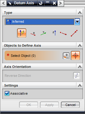
Datum Axis menu with Inferred selected.
Datum Axis
Type
There are various modes of Datum Axis definition, most of which are quite self-explanatory.
Inferred - Infers a convenient axis based on selected objects.
Intersection - Defines an axis at the intersection of two planar faces. This intersection may be some distance off the object if the faces never actually touch, but NX will not permit selection of parallel planes.
Curve/Face Axis - Defines an axis through the center of a curved surface (the central axis of the cylinder containing this surface).
On Curve Vector - Defines an axis passing through a specified location on a curve. Location may be expressed (in "Location on Curve") absolutely or as a percentage of the arc length. The axis at this location may be oriented tangent, normal, or bi-normal to the curve, or parallel or perpendicular to the object.
XC-Axis - Defines an axis through the origin in the same direction as the x axis.
YC-Axis - Defines an axis through the origin in the same direction as the y axis.
ZC-Axis - Defines an axis through the origin in the same direction as the z axis.
Point and Direction - Defines an axis through a selected point, oriented either parallel or perpendicular to a selected line.
Two Points - Defines an axis through 2 selected points.
Axis Orientation
Reverse Direction reverses the direction of the datum axis.
Settings
Scale Factor changes the display size of the CSYS.
The associative option causes the Datum Axis to relate to its parent features parametrically.
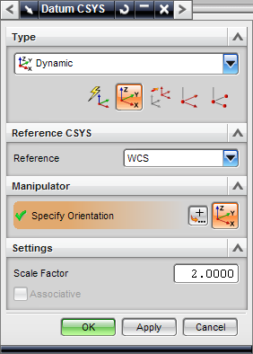
Datum CSYS menu with Dynamic selected.
Datum CSYS(Coordinate SYStem)
Type
There are various modes of Datum CSYS definition, most of which are quite self-explanatory.
Dynamic - Defines a CSYS by allowing you to translate and rotate the CSYS manually.
Inferred - NX infers a convenient CSYS based on the objects you select.
Origin, X-Point, Y-Point - Defines a CSYS using 3 points. Point 1 is the origin. Point 2 defines the x axis as the vector connecting points 1 and 2. Point 3 defines the y axis as the vector connecting point 1 and the projection of point 3 onto the plane normal to the x-axis.
Three Planes - Defines a CSYS using 3 planes. Plane 1 is the normal plane to the x axis. Plane 2 is the normal plane to the y axis. Plane 3 is used to define the origin, which is the intersection of the 3 planes.
X-Axis, Y-Axis, Origin - Defines a CSYS by allowing you to select an origin and x and y axes. If the x and y axes are not perpendicular, NX leaves your x axis definition and infers a y axis.
Absolute CSYS - Defines a CSYS with the same origin and axes as the absolute CSYS. You may want to use this option if you want to scale up an absolute system.
CSYS of Current View - Defines a CSYS based on your current view orientation. The origin is the center of the window, the x axis is parallel to the bottom of the window, the y axis is parallel to the side of the window, and the z axis is out of the board.
Offset CSYS - Defines a CSYS offset from another existing CSYS. Select the other existing CSYS in Reference CSYS (it may be the work system, absolute system, or another existing selected system). Then, specify the translational offset, rotation about each axis, and order of operations.
Settings
The associative option causes the Datum CSYS to relate to its parent features parametrically.
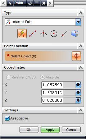
Point menu with Inferred Point selected.
Point
Type
There are various modes of Point definition, most of which are quite self-explanatory.
Inferred Point - Select an object and NX will infer the mode of point definition you intend to use. Includes Cursor Location, Existing Point, End Point, Control Point, and Arc/Ellipse/Sphere Center.
Cursor Location - Creates a point at the location you click.
Existing Point - Creates a point on top of the selected existing point.
End Point - Creates a point at the end of a line or curve.
Control Point - Creates a point at the control point nearest to the clicked location. Often this is the center or endpoint of a curve.
Intersection Point - Creates a point at the intersection of two curves or of a curve and a surface.
Arc/Ellipse/Sphere Center - Creates a point at the center of an arc, ellipse, or sphere.
Angle on Arc/Ellipse - Creates a point at an input angle on a selected arc or ellipse. Angle on curve allows you to set the angle of the point along the arc.
Quadrant Point - Creates a point at the nearest quarter point of an arc or ellipse.
Point on Curve/Edge - Creates a point on a curve or edge, at the clicked location.
Point on Face - Creates a point on a face at the clicked location. Location on Face is specified by the U and V Parameters. The U and V Parameters run from 0 to 1 each and specify a fraction of the length and width of an imaginary rectangle superscribed on the face. For this reason, (U,V)=(0,0) and (U,V)=(1,1) are often not even on the face.
Between Two Points - Creates a point somewhere on the line (which can be an imaginary line) between two selected points. % Location allows you to set the position of the point along the line.
Coordinates
Relative to WCS allows a point's coordinates to be specified relative to a Work Coordinate System.
Absolute allows a point's coordinates to be specified relative to an Absolute Coordinate System.
X, Y, and Z fields are used to input coordinates of the point being created.
Settings
The associative option causes the point to relate to its parent features parametrically. If this box is not checked, the Point becomes a Fixed Point. Points specified as Relative to WCS or Absolute must be Fixed Points.