MEAM.Design - Laser Cutting - DWGeditor
The Seven Easy Steps to Happy Laser Cutting with DWG Editor
| 1 | OPEN | Open your DWG file in SolidWorks DWG Editor 2009 (can be found under MEAM Shop Software on the PCs in the laser cutting lab). |
| 2 | COPY | Select all of the geometry that you want to cut, and copy it (Edit>Copy, or Ctrl-C). |
| 3 | NEW | Create a new file (File>New or Ctrl-N). In the dialog box that appears, ensure that Use a template drawing is selected, click Next >, then Finish. You should now see a large white rectangle on the screen (this rectangle corresponds to the bed of the laser cutter). |
| 4 | PASTE | Paste your geometry (Edit>Paste or Ctrl-V) within the rectangle, and drag it to the area where you would like to cut. |
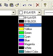
| 5 | COLORS | To set how the laser will treat your geometry, you need to change the line colors. Do this by selecting a line, then choosing a color from the drop down menu in the toolbar. Note that everything at the same color will be treated similarly by the laser cutter (including the WHITE border - i.e. don't leave your parts white!). The standard colors are:
To set up a raster etch field, see the Defining Raster Etch Areas section below. |
| 6 | PENS | Configure the laser by selecting File>Print Setup..., select the appropriate laser (Laser 1 or Laser 2) from the drop-down menu, then click the Properties... button.
If you want to preview with the bounding box (to help locate your stock in the laser bed), set CYAN to VECT, and all the others to SKIP. Otherwise, ensure that the �Pen Mode� is correctly set for each color: SKIP for black
VECT for RED (vector cutting)
VECT for YELLOW (vector etching)
RAST for GREEN (raster etching)
SKIP for everything else
Then set the "Power", "Speed", and �PPI� for each color depending on the material type and thickness (see Cutting Parameters) Click "OK", "OK" when complete. |
| 7 | Ensure that the appropriate laser cutter is turned on, then select File>Print....
In the Print Area section, select the radiobutton for Window, and in the To: field, enter 32 for the "To: X" and -18 for "To: Y." Click the Print button to send the file to the laser cutter and proceed to Cutting Your Part. (note - you can send your file while another job is being cut, it will simply place it next in the queue.) |
Defining Raster Etch Areas
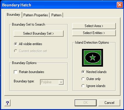
1. Select Insert>Hatch....
2. Change to the Pattern tab, and change the pattern to SOLID.
3. Move back to the Boundary tab, click the Select Entities> button. This will hide the dialog box and give you a selection cursor. Select all the geometry you want to hatch, then hit the Enter key.
4. Click OK and admire your hatched geometry.
5. One last step - to change the color to something other than white, click and drag the mouse over your hatched area to select it, then change the color drop-down.