MEAM.Design - Laser Cutting - AutoCAD
Note: AutoCAD 2006 is only installed on the computers in 167 Towne, and is generally only used for printing parts that were defined in other software (mostly SolidWorks).
The New-and-improved way
1. Log in as gmuser (the password is written on the computer), and start up AutoCAD 2006.
2. If you've got a DWG file from another program, open it, select all the geometry, and select Edit>Copy.
3. Create a new file by clicking on the small new file button at the top left of the screen (for some reason this is not the same as selecting File > New..., which you don't want).
4. Now either paste your geometry (Edit>Paste), or sketch your geometry within the displayed rectangle, and set the colors of the geometry you want to cut to one of the primary AutoCAD colors (we often use red for through cuts, etc.) Note that everything at the same color will be treated similarly by the laser cutter.
5. To set up a raster etch field, see the etching section below.
6. When you're ready to cut your parts, select Plot... from the File menu.
- Select either laser1 or laser2 from the Name: drop-down under Page setup (note - this is different from the drop-down under Printer/Plotter!)
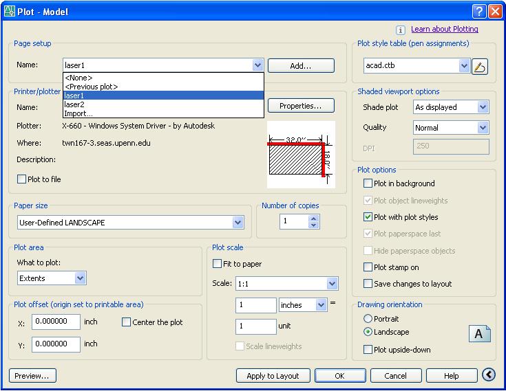
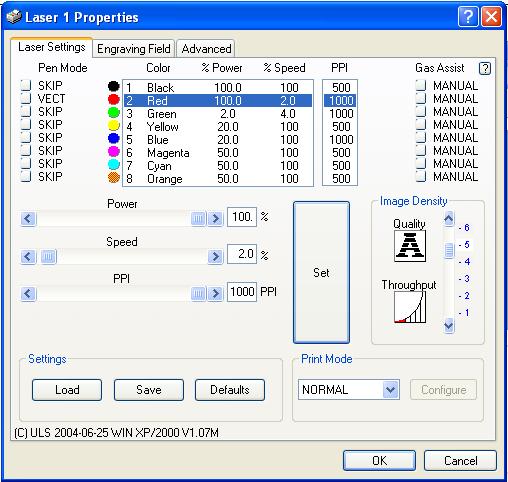
- Click the Properties... button under Printer/Plotter, then click the Custom Properties button. This will open the dialog box where you can configure the cut settings for the different colors. Set all "Pen Mode" settings to SKIP except for the color(s) you would like to cut. Set the colors you wish to cut to VECT for vector cutting or RAST for raster etching. Set the appropriate Power, Speed, and PPI for each color depending on the material type and thickness (Cutting Parameters) and click the huge Set button to store the settings. Note - if you're using Laser 1, the Gas Assist should be set to MANUAL, if you're using Laser 2, it should be set to LOW.
- Click OK twice to get back to the main Plot screen. Confirm that things are set correctly (scale = 1:1, etc.), then ensuring that the laser cutter is turned on, click OK to send the part to the printer. Note - you can send your file to the laser even if it's in the middle of another job, it will just save it in the buffer.
7. Now, proceed to Cutting Your Part.
Defining Etch Areas
Create or paste in the outline of the area you want to etch, select Hatch... from the Draw menu, and follow these steps:
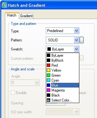
1. Click the pattern next to Swatch:
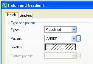
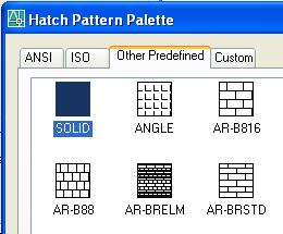
2. Within the box that appears, move over to the Other Predefined tab, select SOLID, and click OK
3. Click again on the (now solid) pattern next to Swatch: and change the color to something else, say Blue.
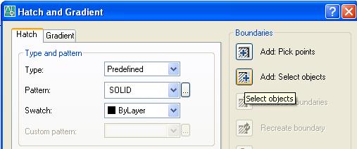
4. Click the button next to Add: Select Objects under Boundaries. This will take you back to your drawing, where you need to select the objects which define the boundary of the section you want to fill. Once you've selected everything, hit the Enter key.
5. Click OK and you should now have filled-in geometry. Now you'll need to remember to properly set the laser settings for the color you chose when you go to Plot.
NOTE: If you want to leave islands in your hatch, click the small arrow button in the bottom-right corner of the Hatch window to show more options.
The Old-School Way
1. Start up AutoCAD 2006, and if you are working from an exported DWG file from another program, go ahead and open it. Otherwise, you'll want to start with a new file.
2. Now, you need to define the laser cutting area.
- Go to the "Draw" menu and select "Rectangle".
- Specify the first corner point at (0,0) and the other corner point at (32,-18)
- Go to the "View" menu and select "Zoom" and "Extents".
3. Either draw your part, or move your existing geometry to be fully located within the rectangle.
4. Set the color of the geometry you want to cut to one of the primary AutoCAD colors (we often use red for through cuts, etc.) Note that everything at the same color will be treated similarly by the laser cutter.
5. (optional) To set up raster-etch fields, (MORE COMING SOON!)
6. Now we're going to define the page setup by selecting Page Setup Manager from the File menu, then select the "New" icon, give it a name, and click "OK". Now you need to set the following:
- Printer/plotter = Laser 1 or Laser 2
- Plot style table = acad.ctb
- Plot area = extents
- Plot scale = uncheck Fit to Paper, set scale to 1:1
7. Continuing on, click Properties under Printer/Plotter to set up a few more things:
- If you need to cut close to the edges of the bed, click on "Modify Standard Paper Sizes (Printable Area)" in the "Device and Document Settings" menu, select the "Modify Icon", and set al values to 0.0.
- Now click on Custom Properties under "Device and Documents Settings", then in "Access Custom Dialog" select "Custom Properties".
- Set all "Pen Mode" settings to SKIP except for the color(s) you would like to cut. Set the colors you wish to cut to VECT for vector cutting or RAST for raster etching.
- Set the appropriate ''Power", "Speed", and "PPI" for each color depending on the material type and thickness (Cutting Parameters)
- If you're using Laser 1, make sure the gas assist is set to Manual, or if you're using Laser 2, set it to Low
8. Click a bunch of OKs to get back to the main screen.
9. Ensure that the laser cutter is turn on (if it's off, flip the orange switch at the lower right back corner of the machine and wait for the LCD screen to show Ready.
10. Now, select Plot from the File menu, select the Page Setup you defined above, verify the settings, and click OK to send the part to the laser.
11. Now, proceed to Cutting Your Part.