MEAM.Design - SAAST - A3: IR Sensors
To be completed by Wednesday, July 9th, this exercise should familiarize you with some of the equipment in the GM lab, as well as a few basic circuit elements including LEDs and phototransistors. This should take between two and four hours to complete, and while you can work together, it is vital that everyone understands the concepts! PLEASE read through all of the steps before you begin. Keep an electronic copy of your answers to the questions in bold and submit them via this Google Form when you are finished. (concise answers are appreciated).
PART 0: WARM UP
0.1 Understanding LEDs
Why is there a 100Ω resistor present in the circuit for part 2.1?
PART 1: METERS, SUPPLIES, AND POTS

1.1 - The Digital Multimeter (DMM)
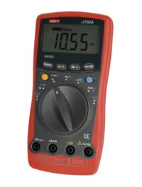
The GM lab tool crib has an assortment of digital multimeters for you to use. These are most commonly used for checking voltages or measuring resistance (though most of them have numerous other functions). Each multimeter should have two test leads attached to it (one red, one black). For the purpose of this lab, we will leave a number of multimeters in a box outside the tool-crib window. Please wrap the test leads around your multimeter and return it to this area when you are finished.
1.1.1 - Inspect your multimeter. The black lead should be plugged into the hole labeled COM (which stands for common, often referred to as ground - as a convention, you should try to always use black colored wires for ground, it will make debugging complicated circuits much easier!). The red lead should be plugged into the hole labeled V/Ω. The multimeter is now set up to read voltage or measure resistance.
1.1.2 - Take a minute to familiarize yourself with the symbols on the multimeter dial.
1.1.3 - Find a battery. Measure the voltage across the terminals. Is the voltage what you expected it to be? Is there a measurable resistance across the battery terminals?
1.1.4 - Set your multimeter to connectivity testing mode (when set to test for connectivity, the multimeter will beep when the resistance between the two probes approaches zero, which can be quite useful when trying to find breaks in circuits that should be connected). See which parts of the bench or table are electrically connected.

1.2 - The Variable Power Supply
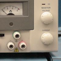
Most desktop power supplies allow the user to adjust the output voltage and/or current of multiple channels, with some type of display to indicate the output parameters. The GM lab power supplies have two variable channels and a fixed 5V channel. Each variable channel can operate in either CV (Constant Voltage) or CC (Constant Current) mode, as indicated by the two LEDs. Only one light will be on at a time. When the CV light is illuminated, the power supply will maintain the output voltage set by the dial, thereby supplying as much current as required to maintain that voltage. Conversely, if the CC light is illuminated, the power supply has reached the current limit set by the current dial, and the voltage will decrease as needed to maintain the desired current.
1.2.1 - Turn on the power supply, and ensure that the switches are set to independent (IND) mode. Turn the current knob for one of the channels all the way up (clockwise). Does the current display change as you do this? Why? Turn the voltage knob. Does the voltage display change as you do this? Why? Does anything happen to the CV and CC lights?
1.2.2 - Note that there are three output connections for each channel: ground, negative (-), and positive (+). Using the DMM, measure the voltage difference between the (-) and (+) outputs as you adjust the voltage knob. Do the multimeter and the power supply agree? Does the current display show any current? Now measure the voltage between the ground and positive terminals. See if you can explain the difference between the ground and negative terminals.

1.3 - Potentiometers
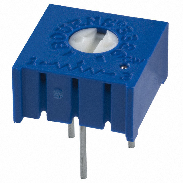
Grab a potentiometer (1k or greater) from the mini-store, and a pair of alligator wires from your tool kit.
Using a multimeter, measure the resistance between the various pairs of leads, and make sure you understand how the three pins of the physical device correspond to the potentiometers in the schematics of Part 1 below. Continued to watch the multimeter as you turn the knob on the potentiometer, and make sure you understand how it works.
Connect one end of the potentiometer to the (+) terminal of the fixed 5V output from the power supply, connect the other end of the potentiometer to (-) terminal of the fixed 5V supply, and connect the multimeter between the (-) end of the potentiometer and the wiper (middle pin). Turn on the power supply and observe the voltage on the multimeter. What happens when you turn the knob on the potentiometer? Can you describe the mathematical relationship between the knob angle and the output voltage?
When you're done, please return the potentiometer to the correct bin in the mini store.
PART 2: OPTOELECTRONICS

2.1 - Emitter
2.1.1 - With a wavelength beyond that visible to the human eye, infrared light is widely used for sensing, control, and communications. In this portion of the lab, you will construct a simple infrared emitter/detector pair to send an analog signal across a short distance.

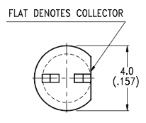
Build the emitter circuit shown above. You should use an LTE-4206 IR LED, a 100Ω resistor, and a 2kΩ potentiometer. Be sure to check the polarity of the LED (the datasheet can be found here - hint: the flat edge is the cathode). Using a cellphone or other camera (most inexpensive digital camera sensors are sensitive to IR light, so they make a great debugging tool for IR signals), look at the front of the LED. Change the resistance of the potentiometer, and do your best to explain what is happening in the circuit to cause the change that you observe (in other words, what is changing when you turn the pot, and how does this cause a change in the light output?). Set this circuit aside while you work on part 2.2.
2.2 - Receiver
2.2.1 - Using an LTR-4206 IR phototransistor (the datasheet can be found here), a 1kΩ resistor, and a 2MΩ potentiometer, build the circuit shown below (if you can, step 2 will be a bit easier if you build this on a different breadboard from the emitter circuit). Be sure to double-check the polarity of the phototransistor before you apply power to the circuit!


2.2.2 - Point the LED and phototransistor at one another (this is most easily done by bending the leads such that they are both horizontal and at approximately the same height), and measure the voltage between the phototransistor collector (labelled "Vout") and ground. See how this voltage changes as you move the LED and phototransistor farther apart. Place the LED and phototransistor approximately 10 cm away from one another and see whether an increase or decrease in the potentiometer in the phototransistor circuit results in an increase in sensitivity. Explain what is happening within the circuit.
PART 3: REFLECTANCE SENSOR
3.1 - If you orient the LED and phototransistor next-to and nearly parallel to one another, you can create a sensor capable of estimating the distance and/or the reflectivity (and thereby greyscale color) of an object. Test this out by rearranging your circuit and moving various objects in front of your newly-created sensor. You will find that there is an optimal sensing distance based upon where the centerlines of the LED and phototransistor overlap. Now, find both a white and black object, and adjust the potentiometers in your circuits to reveal a 1 Volt change in the emitter output when you place each object near the sensor's focal point. Demonstrate your reflectance sensor to one of the TAs and record their name.
PART 4: BREAKBEAM SENSOR
4.1 - Using your emitter and receiver circuits together, you now have a simple breakbeam sensor. If you place an object between the emitter and receiver, the output voltage of the receiver circuit should change. Locate the emitter and receiver about 5 centimeters away from each other and try to keep them as collinear as possible. Adjust the potentiometers to create a 3 Volt change when an object is placed between the emitter and receiver. Record the potentiometer values that you found to work best.
4.2 - Modify the phototransistor circuit to turn off a visible (red, green, or yellow) LED when an object breaks the beam. Describe your modified phototransistor circuit.
4.3 - Demonstrate your working breakbeam sensor to one of the TAs and record their name.
4.4 - Once you are finished, return the potentiometers, LED and phototransistor to the correct bins in the mini store.
SUBMISSION
Don't forget to complete the Google Form (link at the top of the page).