MEAM.Design - MEAM 247 - P1P1: Phidget Introduction
Project 1, Part 1: Phidgets
(due by 2:00 p.m. on Monday, 9/19)
This should take between one and three hours to complete, and while you can work together, it is vital that everyone understands the concepts! PLEASE read through all of the steps before you begin. Questions highlighted in bold need to be answered in this Google Form before the deadline (concise answers are appreciated).

1.1 - The Digital Multimeter (DMM)
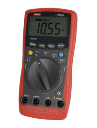
The GM lab tool crib has an assortment of digital multimeters for you to use. These are most commonly used for checking voltages or measuring resistance (though most of them have numerous other functions). Each multimeter should have two test leads attached to it (one red, one black). For the purpose of this lab, we will leave a number of multimeters in a box outside the tool-crib window. Please wrap the test leads around your multimeter and return it to this area when you are finished.
1.1.1 - Inspect your multimeter. The black lead should be plugged into the hole labeled COM (which stands for common, often referred to as ground - as a convention, you should try to always use black colored wires for ground, it will make debugging complicated circuits much easier!). The red lead should be plugged into the hole labeled V/Ω. The multimeter is now set up to read voltage or measure resistance.
1.1.2 - Take a minute to familiarize yourself with the symbols on the multimeter dial.
1.1.3 - Find a battery. Measure the voltage across the terminals. Is the voltage what you expected it to be? Is there a measurable resistance across the battery terminals?
1.1.4 - Set your multimeter to connectivity testing mode (when set to test for connectivity, the multimeter will beep when the resistance between the two probes approaches zero, which can be quite useful when trying to find breaks in circuits that should be connected). See which parts of the bench or table are electrically connected.

1.2 - The Phidget
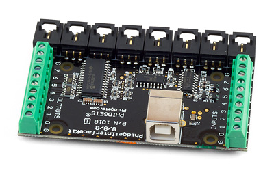
A number of Phidget boards, as show to the right, are available in the Towne 205 lab. Please do not remove them from the lab.
Shown above is the Phidget 8/8/8 USB interface board, which gives you 8 digital inputs, 8 digital outputs, and 8 analog inputs (the manual for the board can be found here: Phidget 8/8/8 Manual (1.9MB PDF), and if you want to run this in a computer outside of the GM or Towne 205 labs, you'll need the drivers from here).
To start using the Phidget, you'll need to download and extract this zip file, which contains the low-level code that Matlab will use to communicate with the Phidget board over the USB port. Once you've extracted this somewhere, create a new Matlab script in the resulting folder. Within the script, you can use the following commands to interact with the Phidget board:
startIK; - Initialize the Phidget (you MUST do this before anything else with the Phidget). If told that no compiler is selected, type "mex -setup", and select either of the Visual Studio compilers. Then type "clear all" to remove all variables from the workspace and try "startIK" again.
stopIK; - Release the Phidget (you MUST do this when you're done with the Phidget).
getAIN(n); - Read an analog input value, where 0<n<7 corresponds to the analog channel. The value returned will be between 0 (0V) and 831 (5V).
getDIN(n); - Read a digital input, where 0<n<7 corresponds to the digital channel. The return value will be 0 (0V) or 1 (5V).
setDOUT(n,s); - Set a digital output, where 0<n<7 corresponds to the digital channel, and s must be either 0 (0V) or 1 (5V).
1.2.1 - Connect a visible-spectrum LED between the terminal labeled 7 on the OUTPUTS side of the board and the terminal labeled G, also on the OUTPUTS side of the board. Make sure that you use the correct polarity, with the anode connected to 7 and the cathode connected to G (which stands for Ground). Note: you can connect the LED directly across the terminals because the Phidget has an internal 250 Ohm resistor on each of the outputs to limit the current.
1.2.2 - Using Matlab, make the LED blink at a frequency between 0.5 and 10 Hertz. If you're looking for some help, see the Matlab page for some really useful tips to get you going. Include a copy of your (well-commented) code in your report.
Phidget Troubleshooting
- Make sure you're running "mex -setup" as detailed on the wiki and using "clear all" afterwards.
- Check connection on a number of different USB ports on the computer. You can check to see if the Phidget is actually connected to the computer by using the "Phidget Control Panel" under the "PACE" programs folder. Many of the front USB ports do not work in Towne 205.
- Make sure you're not shorting power to ground. If your red cable is touching a black cable, that's really bad. It causes the USB port to try to shoot a lot of amps into the circuit, but it will eventually reach the limit where the USB port is shut off and won't recognize your device any more.

1.3 - Potentiometers
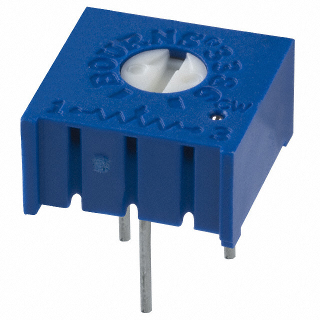
1.3.1 - Grab a potentiometer (1k or greater) from the box in Towne 205 or the mini-store in the GM lab.
1.3.1 - Using a multimeter, measure the resistance between the various pairs of leads, and make sure you understand how the three pins of the physical device correspond to the potentiometers in the schematics of Part 1 below. Continued to watch the multimeter as you turn the knob on the potentiometer, and make sure you understand how it works.
1.3.2 - Grab a Phidget analog connector (see here for more info), and connect one end of the potentiometer to the red wire (5V), connect the other end of the potentiometer to the black wire (GND), and connect the multimeter between GND and the potentiometer's wiper (do not connect the white wire from the Phidget yet). Observe the voltage on the multimeter, and describe what happens when you turn the knob on the potentiometer. What is the relationship between the potentiometer input angle and the output voltage?
1.3.3 - Remove the multimeter, and connect the white wire to the potentiometer wiper. This will connect the wiper to one of the analog input channels on the Phidget, and you will now be able to read the value in Matlab. Update your Matlab code to have the potentiometer control the frequency at which the LED is blinking. Demonstrate your working system to one of your classmates, and include their name in your report. Also include a copy of your code.
1.4 - Completion and Cleanup
1.4.1 - Finish the Google Form questions, and return all hardware and tools to the designated areas in the lab.