MEAM.Design - SolidCAM - 2.5D Milling - Pocket
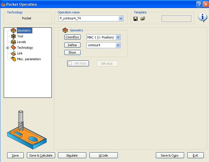
\\To add a pocket operation, right click Operations in the feature tree and select Add Operation > Pocket... This will bring up the following dialog box with four menus: Geometry, Tool, Levels, and Technology, as shown below:
To define the geometry to be milled, select define from the Geometry menu, and the following screen appears:
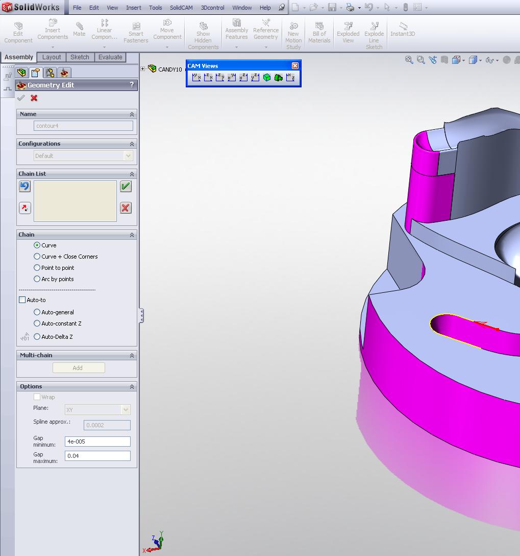
Under the chain menu on the left, select the type of geometry you would like to use to define the pocket. In the example above, curve is being used. In this case, select a closed curve to define the pocket. When you have finished defining your geometry, click the green check box to return to the main menu.
Use the Tool menu to define a new tool or to select one from your existing Tool List.
In the Levels menu, the Clearance Level refers to the z height where the tool is free to rapid quickly across your part. This value should always be significantly above the height of your stock. The meaning of the safety distance is unknown, so just leave it at the magic number of 0.0787 The Upper Level refers to the z height where the tool will start face milling. The Face Depth refers to the z height where the tool will finish face milling. For each of the parameters, you have the option of entering a value directly if you know it, or you can select the appropriate parameter and use your model geometry to define these z values. In the Step Down box, enter the height that you want your mill to take off in each pass. Make sure this is a reasonable number.
Select the Technology menu to define the milling style:
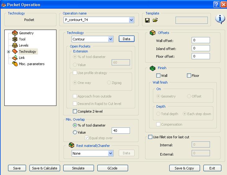
Under Technology, select the style of tool path you wish to mill. Select Data to define more options. Under offsets, enter the values would like to leave for finishing passes, and then check the boxes for wall and/or floor under Finish.
When you are done, make sure to select Save or Save and Calculate before you exit to make sure your operation is saved.