MEAM.Design - SolidWorks - Reference Geometry
Reference geometry is useful when you need to create sketches or features away from either the base datum planes or any existing part surfaces.

Creating Reference Planes

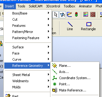
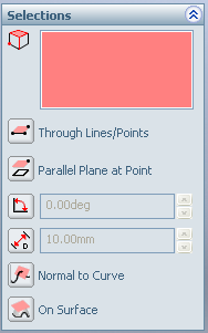
Use mostly for creating sketch planes or mirror planes, these are the most common reference elements that you're likely to work with. To get started, select Insert > Reference Geometry > Plane... , as shown above. This will expose the control box shown to the right. If you select certain geometry in the main window, the selection option will automatically change to what SolidWorks thinks you want. There are a number of options for how you can define the new plane:
NOTE: One other method exists for creating reference planes: If you click the Sketch button while you've got a part edge selected, a reference plane will automatically be created normal to one of the endpoints of the edge, though it won't be visible (yet). You will then be constrained to sketch on this newly created plane, rather than having the chance to select the sketch plane. While this may be considered a feature, most find it rather frustrating. Once you exit the new sketch (even if you don't draw anything), you'll see the new plane. As such, you should always make sure that you don't have any edges selected before you click the Sketch button to start a new sketch.
Creating Reference Axes

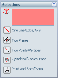
Reference Axes can be very useful for circular patterns and a few other tricks. To get started, select Insert > Reference Geometry > Axis... , as shown above. This will expose the control box shown to the right. If you select certain geometry in the main window, the selection option will automatically change to what SolidWorks thinks you want. There are a number of options for how you can define the new axis:
Creating Reference Points
(...)
Showing Temporary Axes

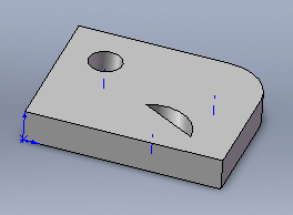
Anywhere that you create a round feature, SolidWorks will create a temporary axis which can then be used for a variety of other operations. While invisible by default, you can view them at any time by selecting View > Temporary Axes (repeat the process to turn them off). The example to the right shows three temporary axes.