MEAM.Design - SolidCAM - Basic Concepts
Basic Concepts
SolidCAM is a CAM editor integrated into the SolidWorks environment. Milling in SolidCAM allows for the fabrication of more complicated parts than would possible/practical using conventional milling or hand-programmed G-code.
SolidCAM + SolidWorks
|
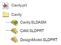
A new SolidCAM file is called a CAM-part. Each CAM-part consists of:
|
Because SolidCAM works within SolidWorks, a CAM-part maintains associativity with the SolidWorks model that it was built from. This applies to CAM-part�s the Stock andTarget bodies. If the SolidWorks model is updated, SolidCAM will reflect the changes automatically or give you the option to synchronize parts.
Opening SolidCAM and Starting a New CAM-part (or loading a saved CAM-part)
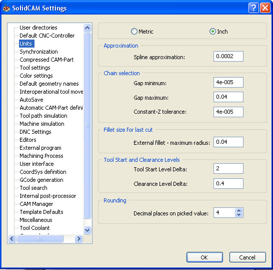
To start a new CAM-part from an existing SolidWorks part, first open your part in SolidWorks. You�ll want to check your SolidCAM unit settings before creating a new part. To do this, from the SolidWorks main menu bar, select SolidCAM > SolidCAM Settings� . Navigate to the Units heading and ensure that Inch is toggled on.
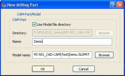
Now, from the SolidWorks main menu, create a new SolidCAM milling part by navigating to SolidCAM > New > Milling. The �New Milling Part� dialog box will open in order to name your part. It is recommended that you save your CAM-part in the same directory as your SolidWorks model (check �Use Model file directory�).
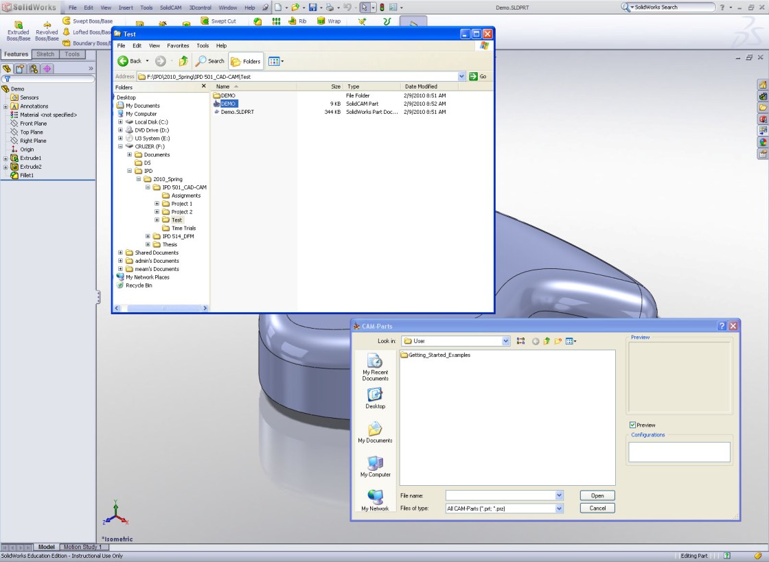
To open an existing CAM-part, first open SolidWorks. From the main menu bar, navigate to SolidCAM > Open. DO NOT try to open your CAM-part from the CAM-Parts dialog box�chances are you won�t be able to locate it. Instead, open Windows Explorer, navigate to the saved file�s directory, and double click on your CAM-part (.PRT file).
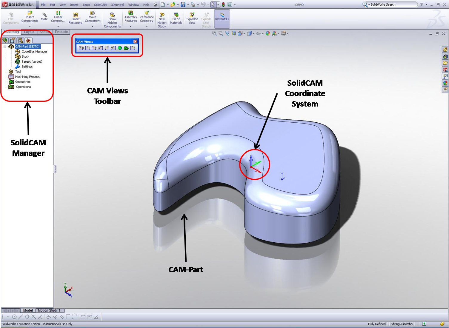
The SolidCAM Interface
The SolidCAM interface consists of the following:
- Machining solid model, or CAM-part
- Coordinate system (often different from the SolidWorks part coordinate system)
- CAMViews toolbar
- SolidCAM manager
High-Level Overview of How to Use SolidCAM
(!) BEFORE STARTING SOLIDCAM:
Design your SolidWorks model with an understanding of the relevant machining tools, processes, fixtures, and constraints for your part.
Within SolidCAM:
- Define a coordinate system, controller, etc.
- Define stock geometry
- Define target geometry
- Add operations
- Verify with Simulations
- Export G-code