.DXF -> .PT4 Conversion for Bubbleheads
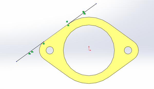
1. Make sure your drawing is fully defined. No discontinuities! Computers don’t like dividing by zero. Also, include your Lead In/Out for your part.
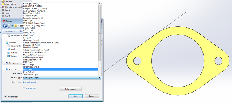
3. Save your part as DXF
4. Just like when you learned how to laser cut in MEAM 101, choose the face you are interested in.
Note: In order to include your Lead In/Out save the file by using the Annotation View that is associated with the geometry you are interested in.
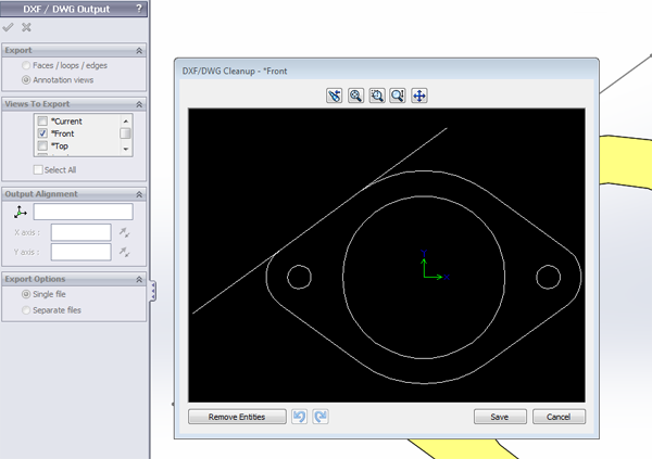
Note: You may encounter a problem with text on your exported dxf file. Solidworks 2013 appends an "instructional use only" text block on top of exported .dxf files. This can cause an error when establishing tool paths. If this is the case, delete the text in 2D Editor, OR chain the path you want to program and avoid clicking near the text block.
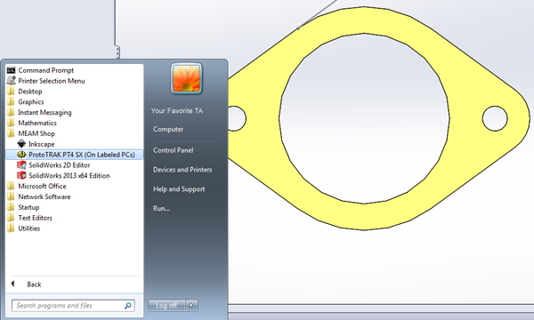
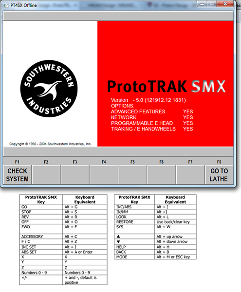
5. Now open the most user friendly, ergonomically designed interface and software of the century: ProtoTRAK PT4 (On labeled computers at GM Lab- under the MEAM folder)
Note: Make sure you familiarize yourself with the Keyboard shortcuts…they will make your life easier
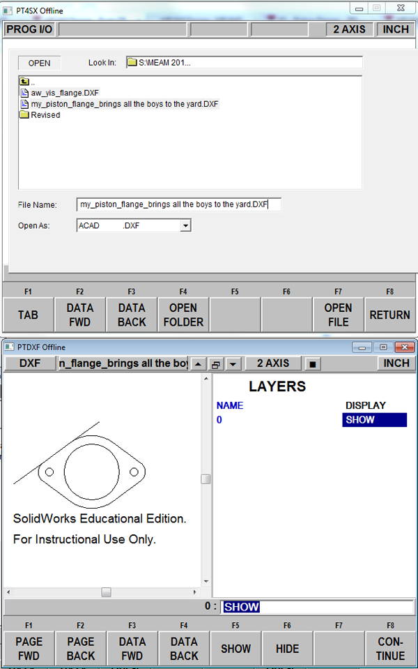
6. Open your newly converted DXF file. To do so, select "alt+m" on the ProtoTRAK software. You will be presented with a series of new menu items at the bottom of the software. Select "PROG IN/OUT", then "OPEN", select open as ".DXF", and navigate to and double click your file. Then select "CONTINUE".
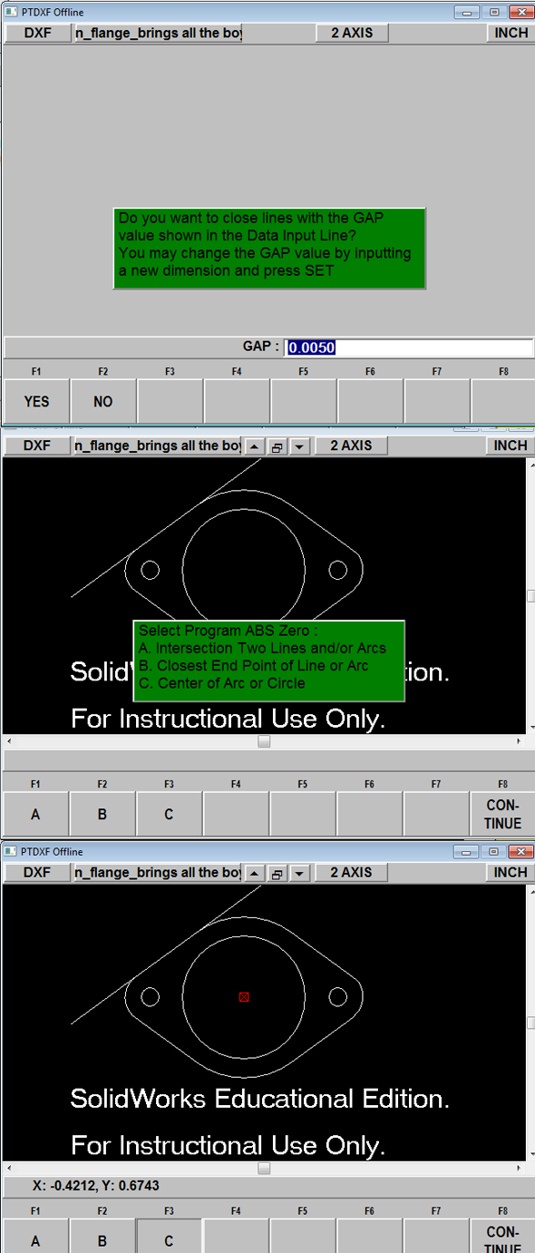
7. Choose the Gap value (you probably won’t be changing this)
8. Select your absolute zero. Be smart about this - let the drawings tell you the location of the absolute zero. After this, when prompted to "add lines", simply click on "CONTINUE".
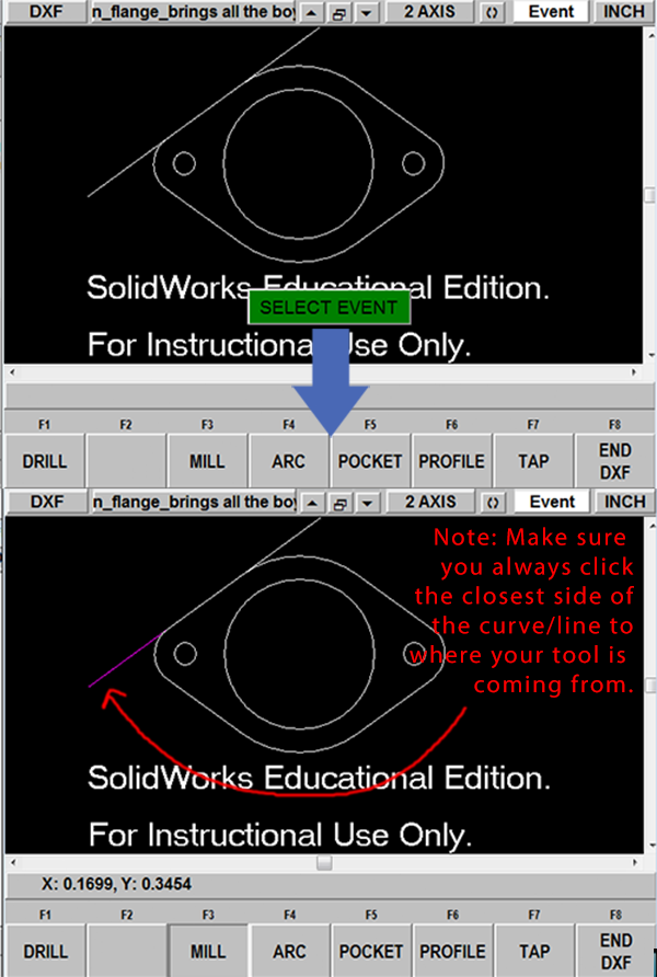
9. Now you can create the outer profile cut. First, select "PROFILE". You will then be queried if you want to chain, which will automatically connect contiguous lines. If you do not chain, you will have to select each element of the outer profile in order of milling event. Now you can start selecting the outer profile lines. If you selected "chain", selecting two elements of the outer profile in order of the milling event will cause the entire profile to be selected. You can then repeat the same process for the pocket in the center of the piston flange by selecting the "POCKET" operation. Select "END DXF" when you are finished.
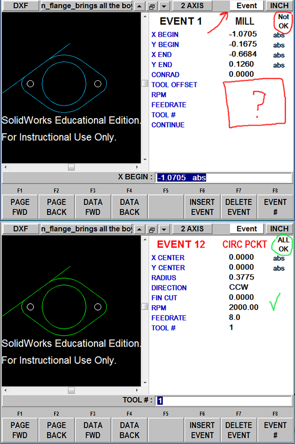
10. While you are in the DXF converter you can select on EVENT on the upper right of the window. You can now view the milling events. You will need to fill in the "TOOL OFFSET", "RPM", "XYZ FEEDRATE", and "TOOL #" for EVENT 1. The values you input into EVENT 1 will propagate through the entire profile cut. You will then have to fill in the similar milling parameters for the pocket (event labelled CIRC PCKT). Select a milling direction that results in a climb mill. If you get the ALL OK you can now END DXF.
11. You will then need to specify a tool diameter. Press "alt+m", select "SET-UP", and select "TOOL TABLE". Enter a 0.2700 diameter rough end mill for tool #1. Note: the diameter of your end mill will be closer to 0.2500. However, 0.02 has been added here so that the milling program can be run a second time for a finishing operation that takes off 0.010.
12. You can now check your tool paths as they would be executed on the ProtoTRAK. To do so, press "alt+m", select "SETUP", and select "TOOL PATH". Verify that the tool path looks as expected. You may encounter errors at this point if you did not fill in all the details for the milling events. Continue fixing any parameter errors and rechecking your tool path until your program is error free.
13. Finally, you want to make sure that you you don't begin or finish a cut at the edge of the feature as this will result in an inferior finish. In other words, if you are cutting the external feature, you want to lead into the cut further out from the edge (a bit more than one tool radius away). In a similar sense, you will also need to continue along a line leading out the the final milling operation. You can do this by adding programmed events at the beginning and ending of the tool path events you just created.
14. All done! Make sure you check your Tool Path before machining!!