MEAM.Design - Senior Design - Team 09 (Alex, David, Jamie, Zach)

The final goal of our senior design project is to design and construct a remote controlled (RC) airplane which we will enter into the SAE Aero Design Contest in the Spring of 2010. We would like to enter our product into the Micro Class which is rated on empty weight versus payload weight. In the micro class, we have a one hundred foot take-off zone, so we will be looking to optimize lift and power while trying to reduce weight as much as possible.
To accomplish this, we will begin by building a model RC airplane from a kit and analyzing its aerodynamic performance in accordance with the competition�s scoring. Once we sufficiently understand the analysis of the model RC plane, we can then optimize the model with our own design in order to improve its performance. There are four major aspects of the design that must be considered when optimizing performance: aerodynamics, propulsion, structures, and controls. Aerodynamically the airfoils must generate as much lift as possible, the plane must be able to take-off within the take-off zone, and the plane must remain aerodynamically stable in flight. Propulsion involves the motor and propeller necessary to power the aircraft. This system must be optimized to support the highest payload, while at the same time remaining as light as possible, as the motor and necessary batteries/fuel are likely to be one of the largest sources of weight. The structure of the aircraft must be made strong and able to withstand the stresses involved during flight, while again reducing the overall weight of the aircraft as much as possible. Finally, we must be able to control the aircraft from the ground. A radio transmitter along with servos will be used to remotely and accurately control the flight of the plane.
Phase I: Build an Off-the-Shelf Kit Airplane
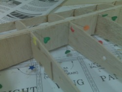
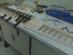
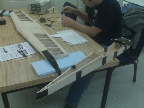
Wings built from parallel ribs connected to spars on top, bottom, leading edge, and trailing edge.
Vertical-grained webbing helps strengthen rib to rib connection.
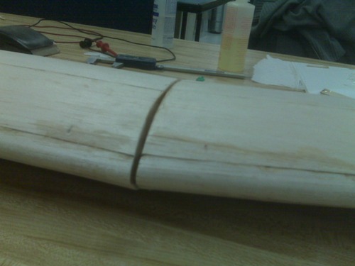
Oh No! A 1/8" gap has formed when joining our wing together (due to the manufacturer's specified dihedral angle). What will we do?!?!?
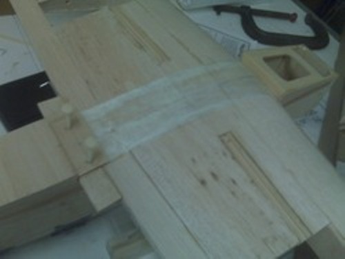
Our method for fixing the gap was to inject it with gap-filling epoxy and harden a strip of fiberglass all the way around the wing. This should provide ample support to sustain the dihedral angle.
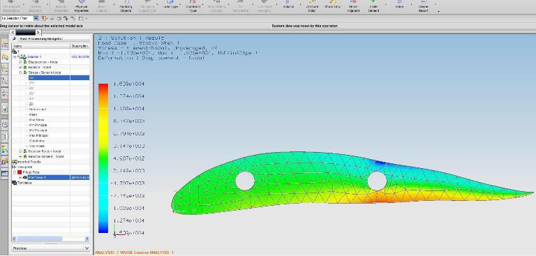
Analyze the Wings
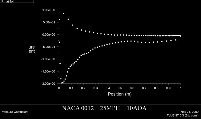
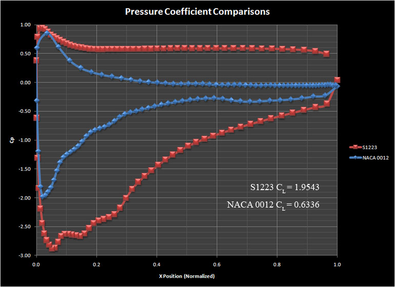
Our off the shelf kit uses a wing similar to the NACA 0012 series airfoils. This is a symmetric wing that is 12% thick at 30% of the chord. Attach:NACA0012.jpg Δ Using Fluent, it was possible to determine the pressure distribution across the wing, which was then used to calculate lift performance. The Coefficient of Lift (CL) was determined to be approximately 0.6 at 25MPH and 10�AOA.
We then proceeded to design a new wing that would be optimal for the requirements of the SAE Aero competition. One important factor in the design of airfoils is the Reynolds number at which the aircraft is going to fly at. The Reynolds number (Re) is a dimensionless number that relates the inertial forces of a fluid to its viscous forces. Re = pvd/u where p is the density of the fluid (in this case, air), V is the velocity of the fluid (airspeed), d is the chord length of the wing and u is the viscosity of air. Thus, as velocity and wing chord increase, the Reynolds number increases.
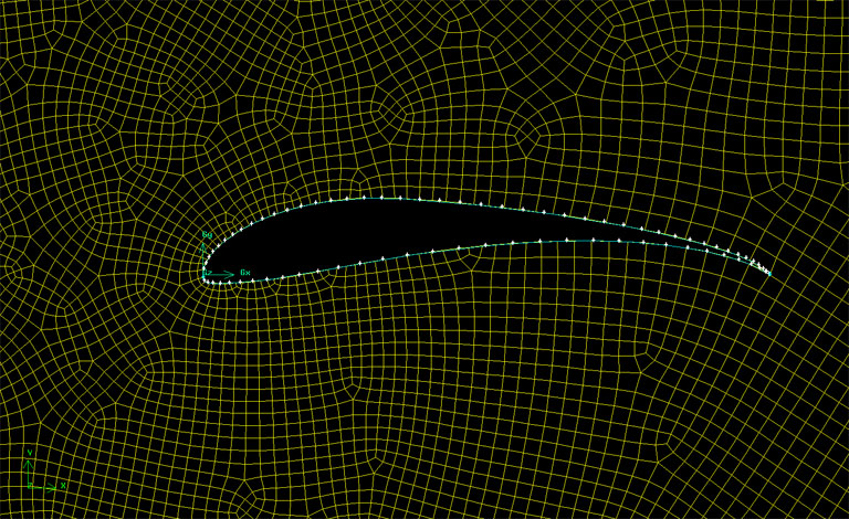
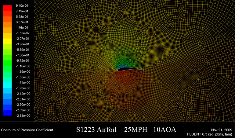
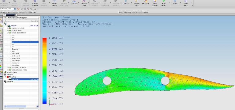
A conventional aircraft flies at speeds where Re is larger than 1,000,000 and, for large aircraft, Re can exceed 10,000,000. However, because our RC aircraft has a relatively short wing (9 inches in length) and will be flying slow (approximately 25mph), the wing will fly at a Re much lower than that of traditional airfoils (Re ~ 150,000). This creates design issues because conventional airfoils do not perform well at these Reynolds numbers because the airflow�s boundary layer separates from the wing very easily. Therefore, it is important that our plane uses a wing designed for low Reynolds number flight. The new wing follows the style of a S1223 Airfoil, which is optimized for light aircraft flying at low Reynolds numbers. Attach:S1223.jpg Δ
The new CL was determined to be 1.9 at 25MPH and 10�AOA.
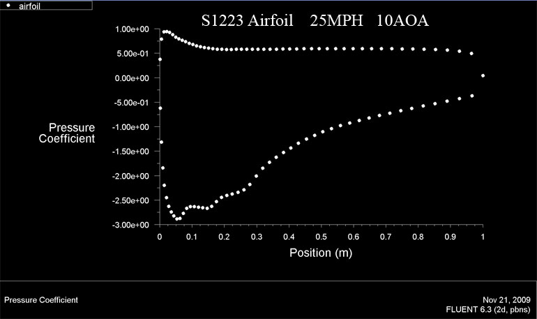
For comparison, the two pressure coefficients are plotted for each wing below:
(:commentboxchrono:)