Shell
The Shell feature is used to create a shell from a solid body by hollowing out the inside. It can be found on the Feature Operation Toolbar or by Insert->Offset/Scale->Shell.
Shell on the Feature Operation Toolbar
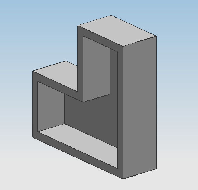
Shell with 1 face removed
Type
Remove Faces, Then Shell
This shell type allows you to select one or more faces to remove before shelling out the interior of a body. This allows you to see the shell from the body's exterior.
Shell All Faces
This shell type will shell out the interior of a body without removing any of the faces after you select the body to shell. You will not be able to see the shell from the exterior unless you cut into the body after shelling.
Thickness
Specify the desired thickness of your shell walls. You may also Reverse Direction if you want to shell outwards (this will cause the hollow to be the full size of the body).
Alternate Thickness
If you do not want uniform shell wall thickness throughout your part, select the faces whose walls will be a different thickness than the primary thickness you specified in Thickness and input this alternate thickness in the appropriate field. As before, you can Reverse Direction of this thickness.
You can also create a shell with more than one alternate thickness. Once you have selected all the faces whose walls have the aforementioned alternate thickness, click Add New Set. Your first alternate thickness and the faces it applies to will appear in the List below, and you can select a second set of faces and input a new alternate thickness for them.
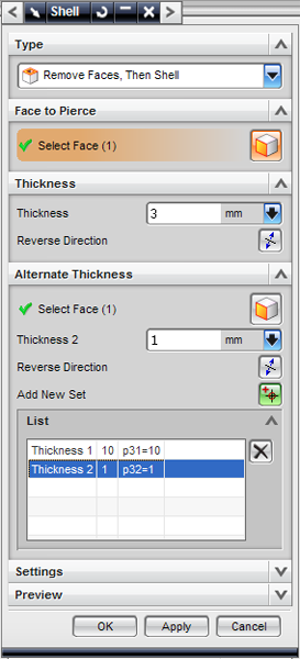
The shell menu Lists all of the
alternate thicknesses.
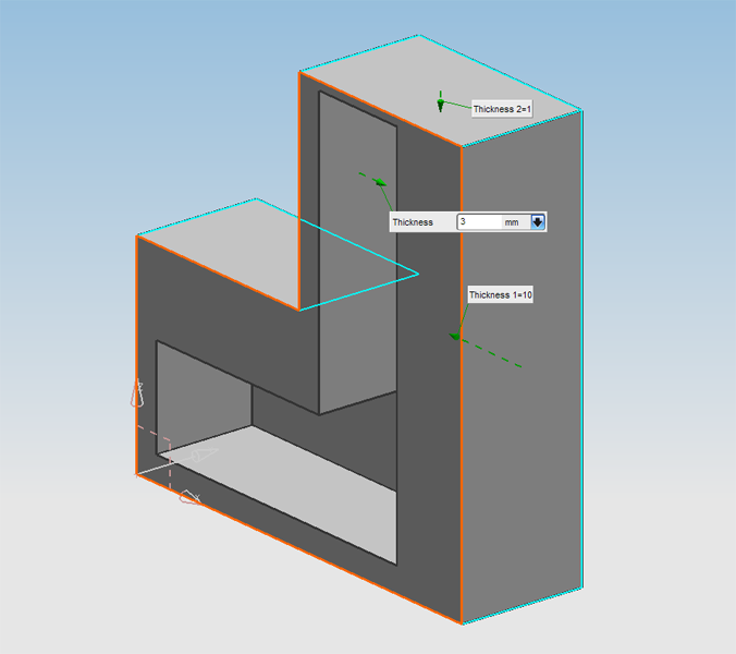
This body has 1 primary thickness and 2 alternate thicknesses.
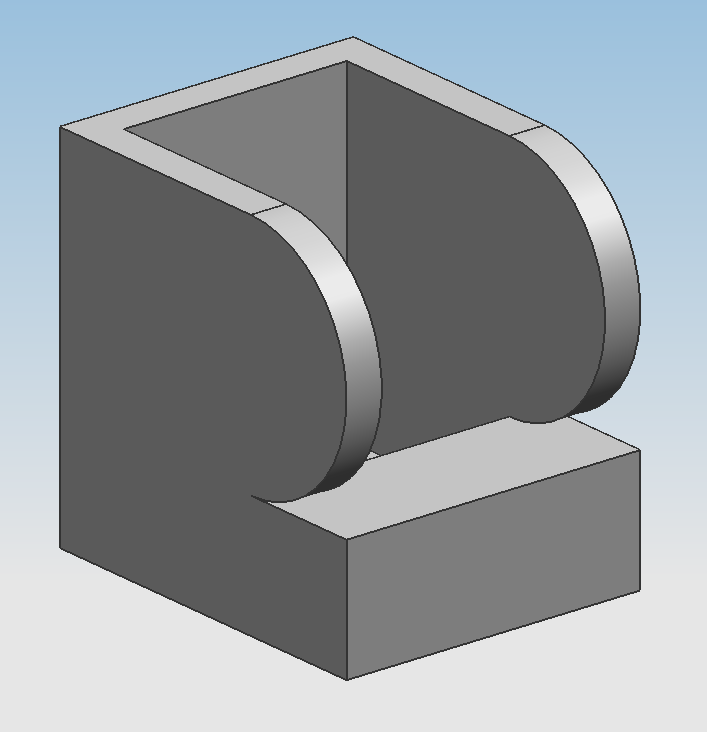
Demonstration of Extend Shelf Face at Tangent Edge
Settings
Tangent Edges
This parameter is only relevant if one of the faces being removed is tangent to one or more non-removed faces.
The Extend Shelf Face at Tangent Edge option allows edge faces to be created along the tangent edge before any of the shelling offsets occur.
The Extend Tangent Face does not create edge faces for along a removed tangent face's edges.
Approximate Offset Faces
This option instructs NX? to fix errors caused when a Shell feature would cause a part to self-intersect. This self-intersection is repaired by generating an approximate geometry.
Tolerance
This tolerance is used specifically for the approximations generated by Approximate Offset Faces and overrides the program's Distance Tolerance?. This value is the maximum disparity between the generated approximation and the impossible, self-intersecting exact solution.
Preview
The Preview checkbox is checked by default and allows you to see the effects of changing the parameters of your Shell feature as you change them.
The Show Result icon is unselected by default. By selecting it, the rest of the Shell feature parameters become grayed out, the selected faces become unhighlighted on your part, and the thickness measurements disappear from your part. Essentially it lets you look at the effects of your Shell feature without any visual obstructions.