MEAM.Design - S62 - Through Hole Plating Process
<< | S62 | >>
# Getting Started
Ensure the S62's on-switch is in the 'ON' position. It is located inside the enclosure, adjacent to the power cord near the front of the machine.
Double click the Board Master icon on the desktop. When it starts, there may be a dialog window, as shown below. Click 'OK' to continue.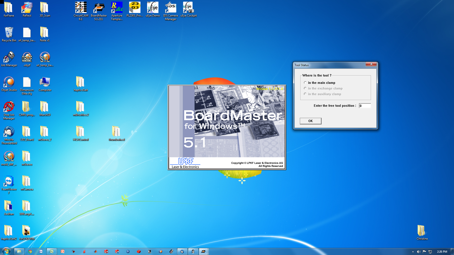
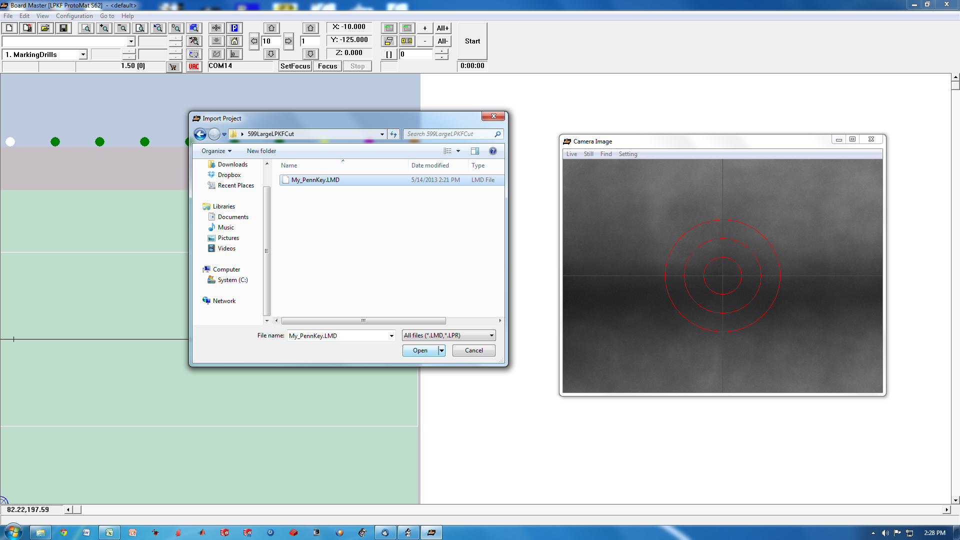
When the software first starts, you will see a blank screen, as shown below. 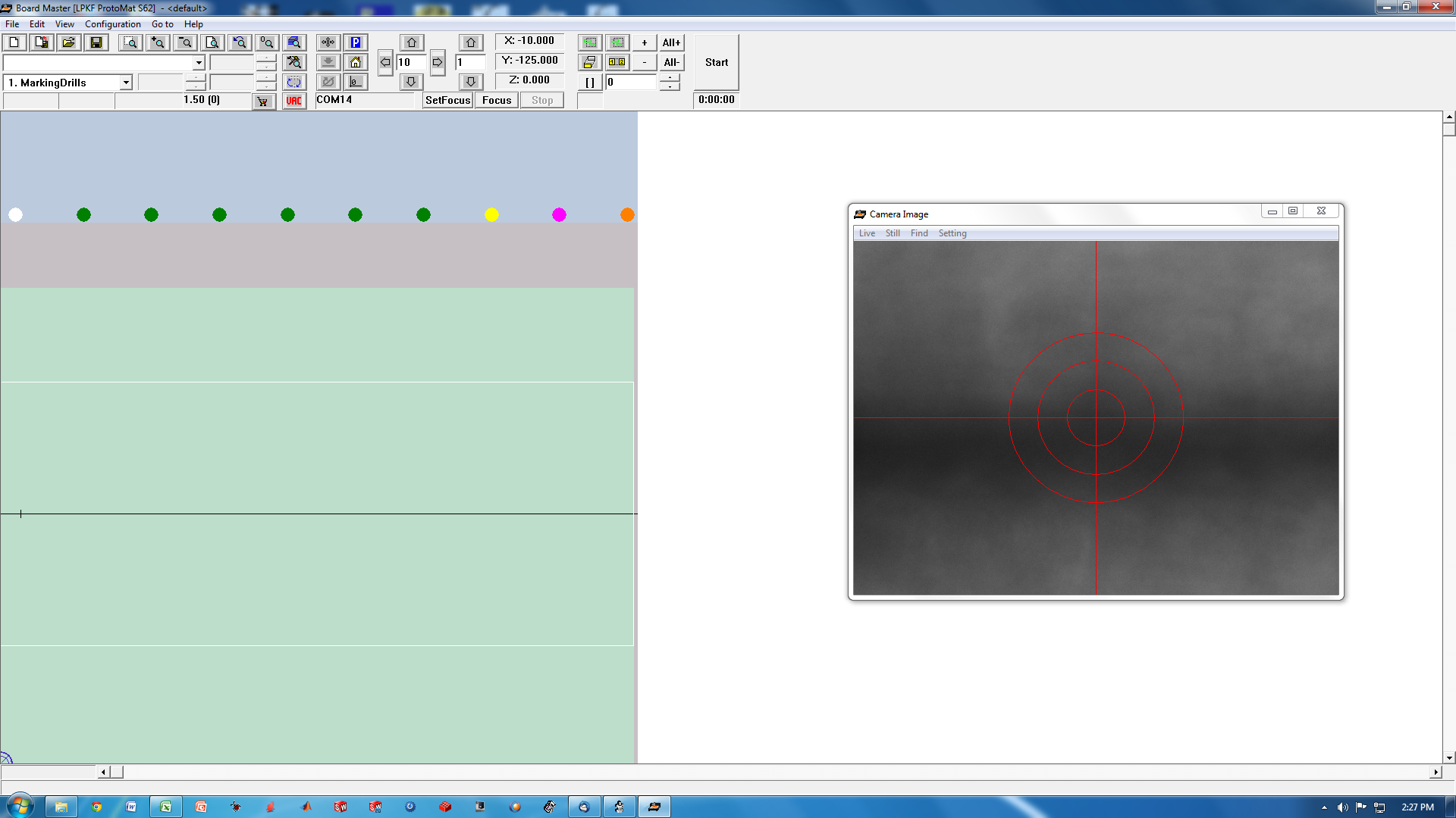
The toolbar in the Board Master software has many buttons. Some are used often, others not at all. Their functions shown in the screen image below.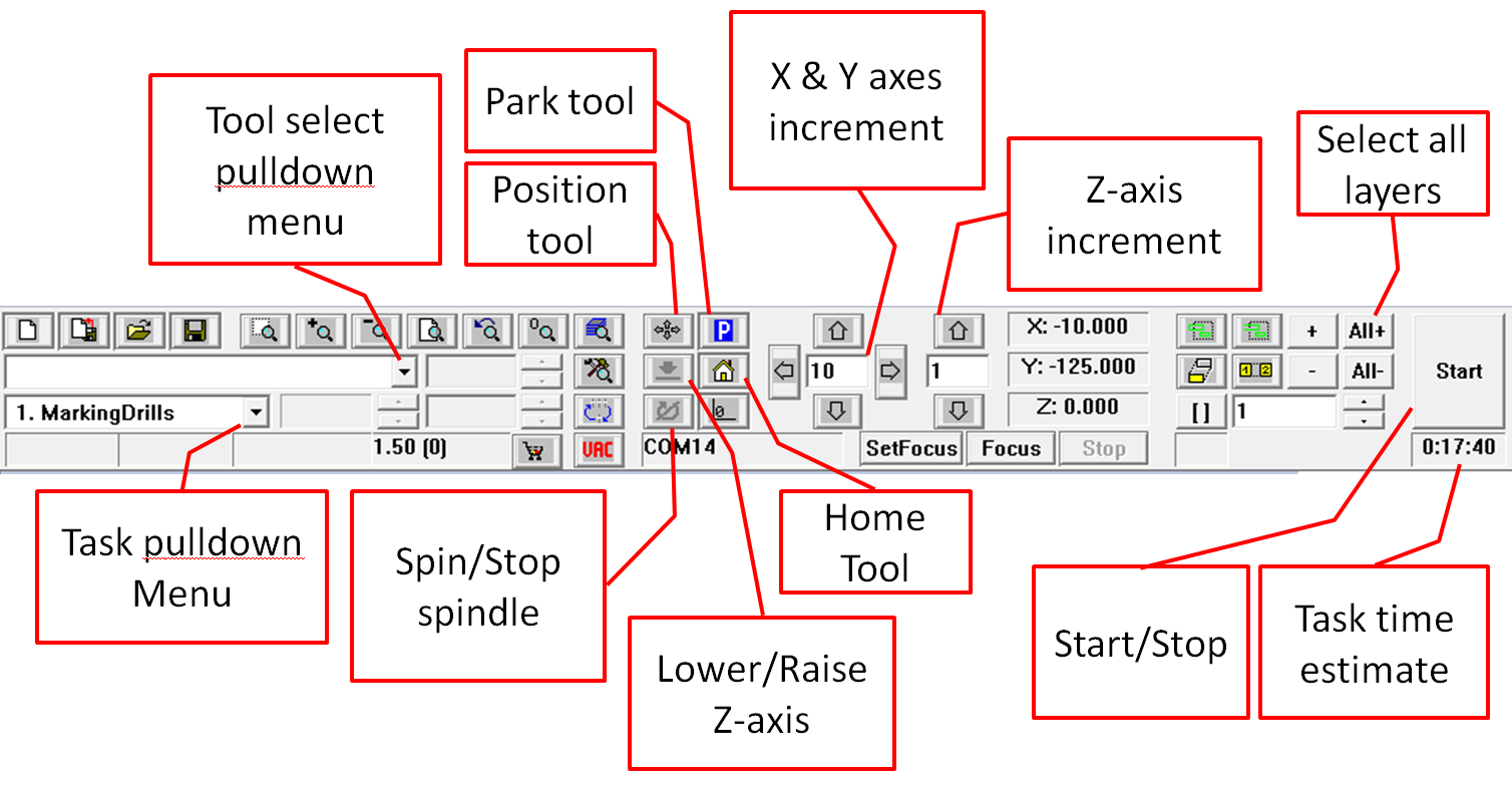
Navigate to the import menu, and import the .LMD file that you exported from the Circuit CAM software.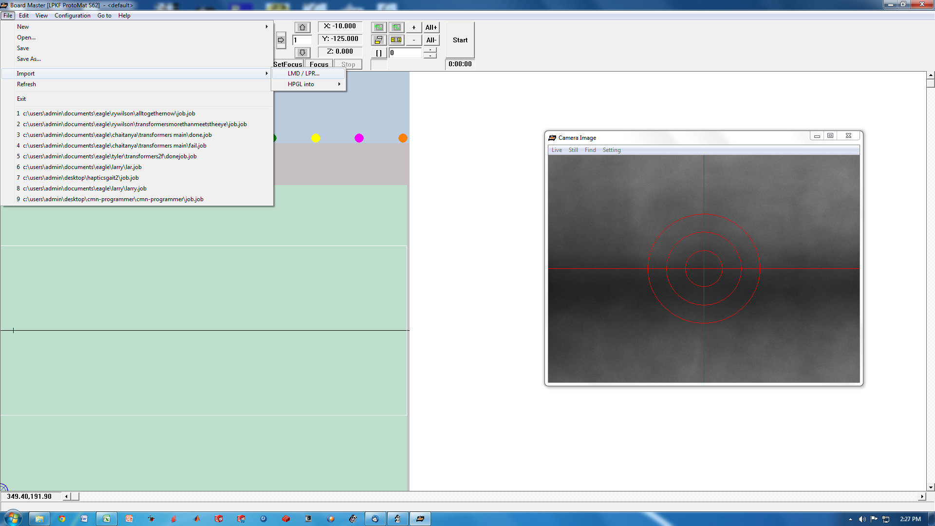
# Marking Drills
Move the milling head of the S62 to the 'park' position using the 'park' button. Place the PCB (with stickers already on it) onto the white fiber board on the S62's milling table.
Turn on the vacuum system, which is located beneath the S62 table. 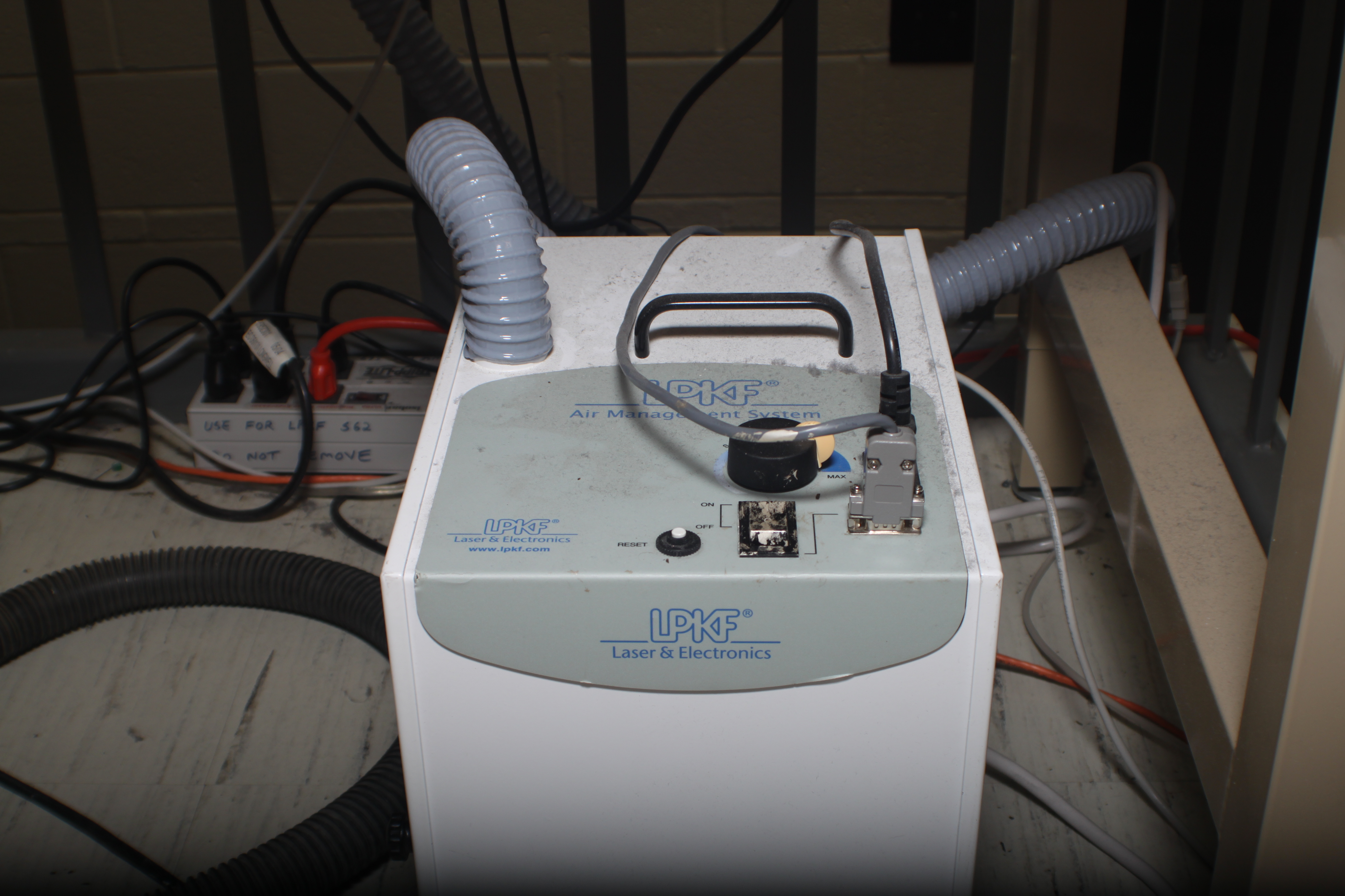
Press the 'Select All Layers' button. Select the 'Marking drills' task from the Task Pulldown Menu. Press 'Start'.
A dialog box will appear, as shown below. This indicates that the S62 wants you to add the tools into the tool holders that it needs for the task it is about to do. Press 'OK'.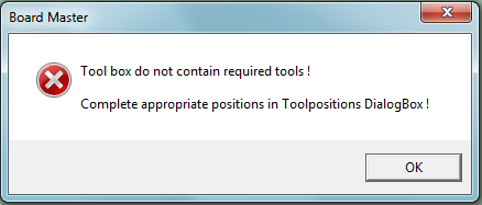
The S62 will want to move the spindle into the 'PAUSE' position to allow you to change the tools in the tool holders. A a dialog like the one below will appear. Click 'YES'.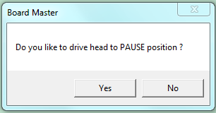
The 'Tool Position' Menu will appear. The left list has several pulldown menus. You use these to tell the S62 which tools you have put into it's holders. They are numbered 1 - 10 from left to right.
Do not use tool holder 1. In the past, it has become jammed several times. Leave it empty.
The right list tells you which tools the S62 needs in order to complete the task that you are presently working on. In this step (the 'MarkingDrills' step) it has a number adjacent to the 0.2mm Universal Cutter and the 1.5mm Sprial Drill, indicating those are the ones it wants to use.
You must ensure that these tools are installed in the tool holders, and then tell the S62 which positions they are in, using the pulldown menus on the left. 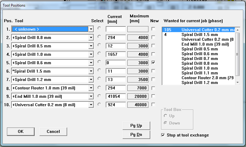
In this case, the 1.5mm Spiral Drill was already in position 6, so nothing had to be done with that tool.
The 0.2mm Universal Cutter was already in position 10, but it was not selected as a marking tool, so the S62 considered it unavailable for this task. Change it to '0.2mm Universal Cutter Marking' to tell the S62 that you intend to use it for this task (the 'MarkingDrills' task).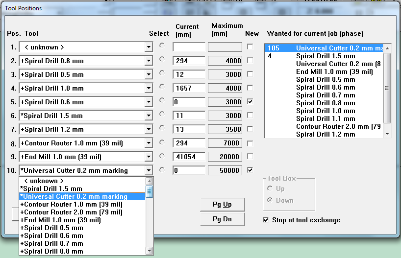
Press the 'OK' button.
The S62 will pick up the first tool that it needs, and position itself to begin the first step of the MarkingDrills task.
The S62 doesn't have a method for determining if the tool tip has the correct z-position by itself. A dialog will appear like the one below, asking you if you want to check and adjust the z-poisition before you start.
It is a good idea to always verify the z-position after a tool has been picked up, in case the chuck is gripping the shaft at a different height compared to the last time it was used. Also, it is common that the z-position is adjusted between tasks, so now is a good time to ensure it is correct for this step.
A dialog will appear, asking you if you want to adjust it. Click 'YES'.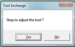
Use the 'Position' Tool to move the spindle above an area of the board you don't mind marking (an area outside the rubout area you defined in CircuitCAM)
Start the spindle (make it turn).
Lower the spindle so the tool bites into the board, by pressing the raise/lower spindle button.
Now raise the spindle by pressing the 'raise/lower' spindle button a second time.
Park the spindle by pressing the 'Park' button.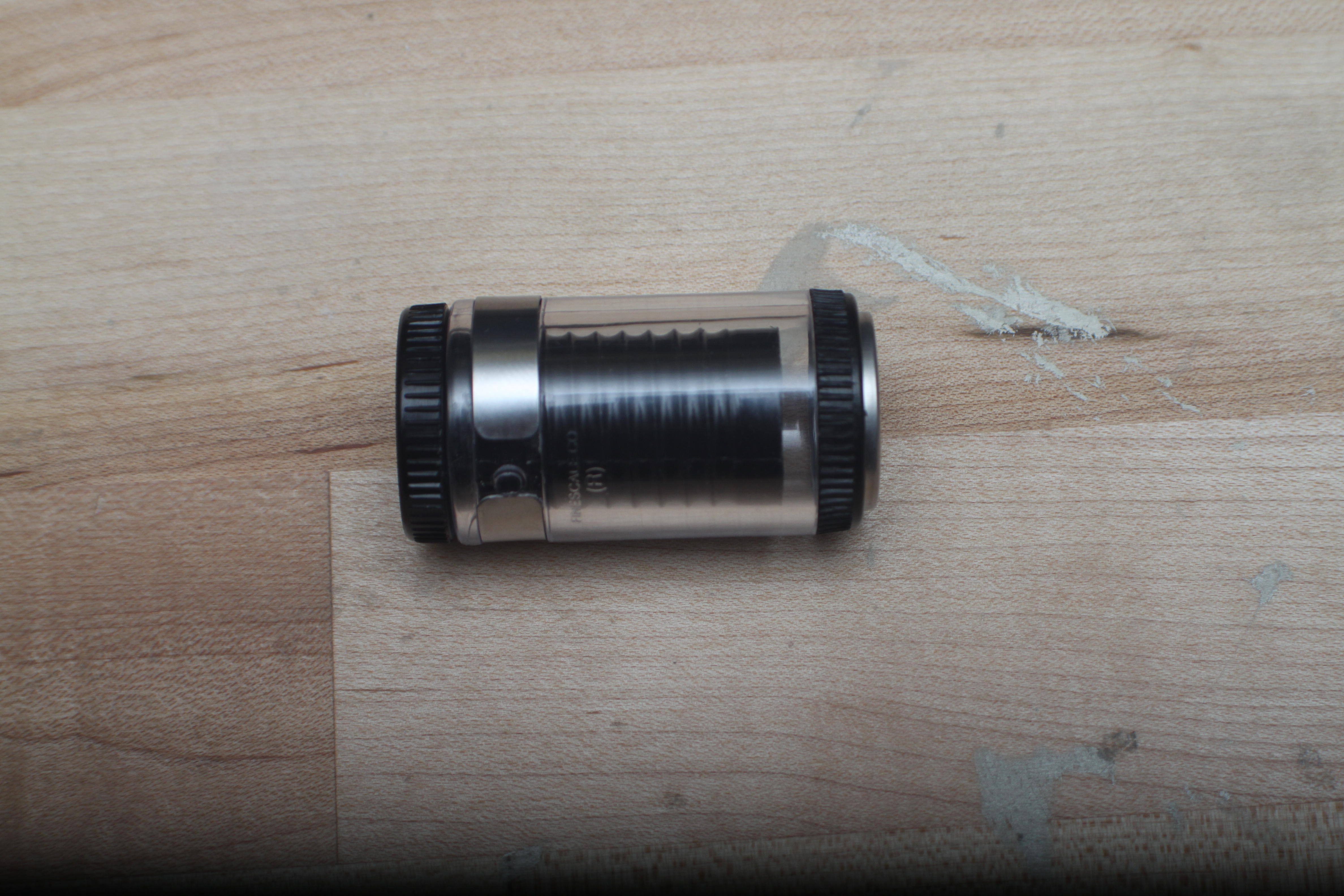
Open the cover and use the magnifying loupe to check the size of the mark that was made by the tool on the surface. Since the 0.2mm marking step is meant just to perforate the plastic sticker you should observe very small marks or dimples in the sticker.
If the tool did not touch the surface, or if the tool made a very deep mark, the z-axis must be adjusted down/up by rotating the collar of the spindle clockwise or counter-clockwise. The spindle collar is the black knurled ring, shown below. 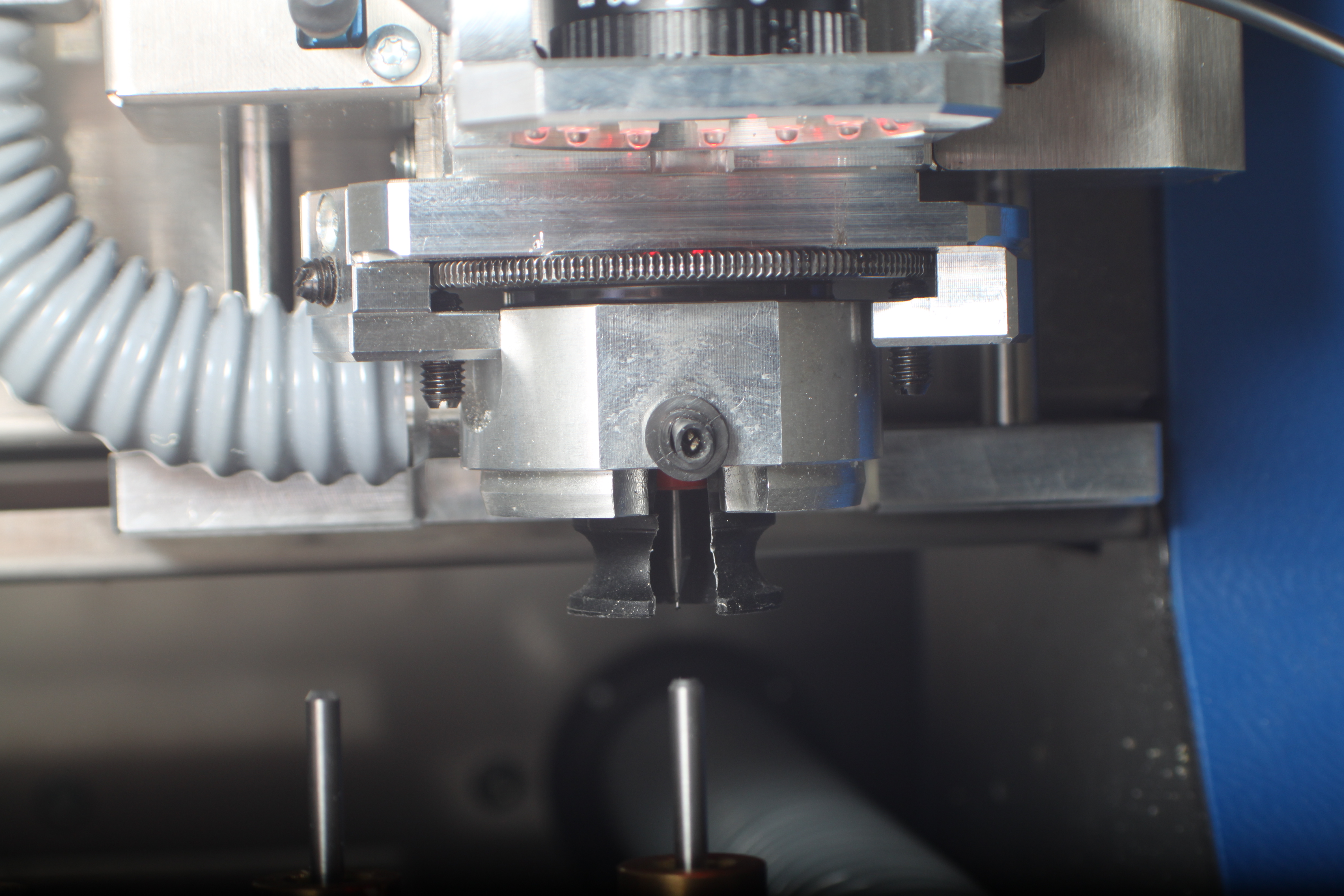
Adjust the spindle and make new markings on the surface of the board until the z-axis height is correct.
Once you have the z-axis set, move the spindle back to the 'Park' position.
You're ready to continue with the MarkingDrills task. Do not select any other tasks from the Task Pulldown Menu, or press any other buttons. Simply press the 'Start' button, and the the S62 will recall what it was doing before you made the adjustments to the z-positon.
Watch carefully as the spindle moves over the board and begins the marking step.
When the marking is finished, the S62 will switch to the 1.5mm spiral drill and drill the 4 fiducial holes you picked in CircuitCAM.
When this is complete, the following dialog will appear: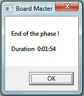
Click 'OK'. You are now done the 'MarkingDrills' step, and you can begin the 'DrillingPlated' Step.
# Drilling Plated
Use the task pulldown menu to select the 'DrillingPlated' step.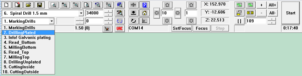
The Tool Positions menu will appear again, because the tool holder generally won't have a very broad selection of drills left in it after the previous step. Like before, the right-hand side list will indicate which drills are necessary, and a number will be displayed adjacent to each item in the list, indicating how many times it will be used. The left list will show what is in the tool holders. When you open the pulldown menus, you can see a star next to the ones which are needed. Just like in the previous step, you must change which tools are in the holders, and also update the corresponding items in the left-side list so that Board Master knows which tools you have have put in the S62. 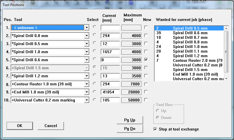
When you're done, the left and right lists should match (as shown below). If there are additional items in the tool holders which seem unnecessary, just leave them in place. You might need them in the upcoming steps. Board Master won't touch them if it doesn't need them. Now press 'OK' and watch carefully as the S62 drills all the holes. Once it's finished, park the spindle, and open the cover.
# Plating
Pretty soon, you'll have to bake your circuit board, so take the time now to preheat the oven. Set it to 10 minutes (which is about enough time to pre-heat it) and set the temperature as shown in the image below.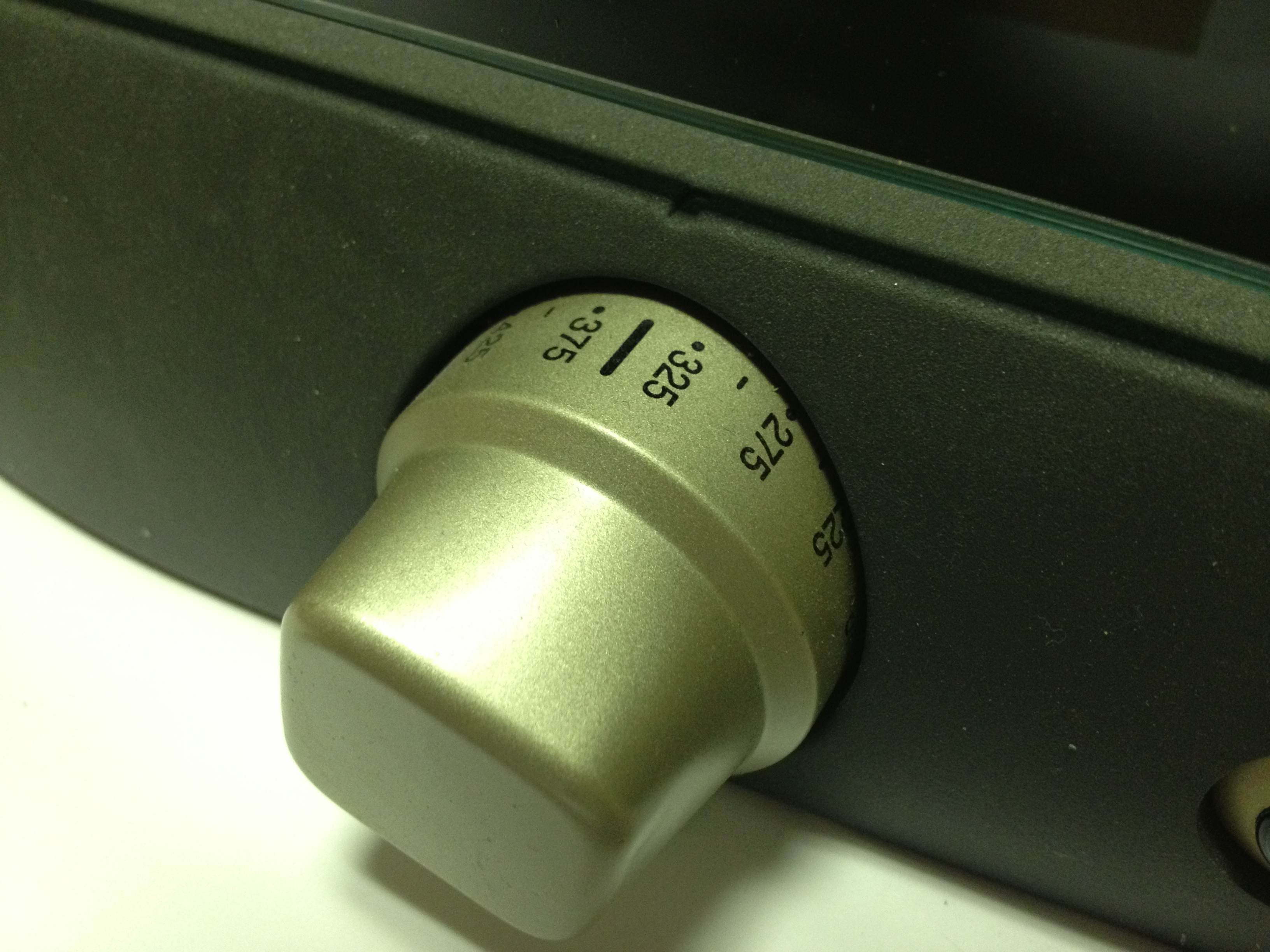
Turn off the vacuum system. Remove the circuit board, and the fiber-board from the table of the S62, so you can see the grooves in the vacuum table. Get the honeycomb tray, and place it in the spot where the fiber-board used to be.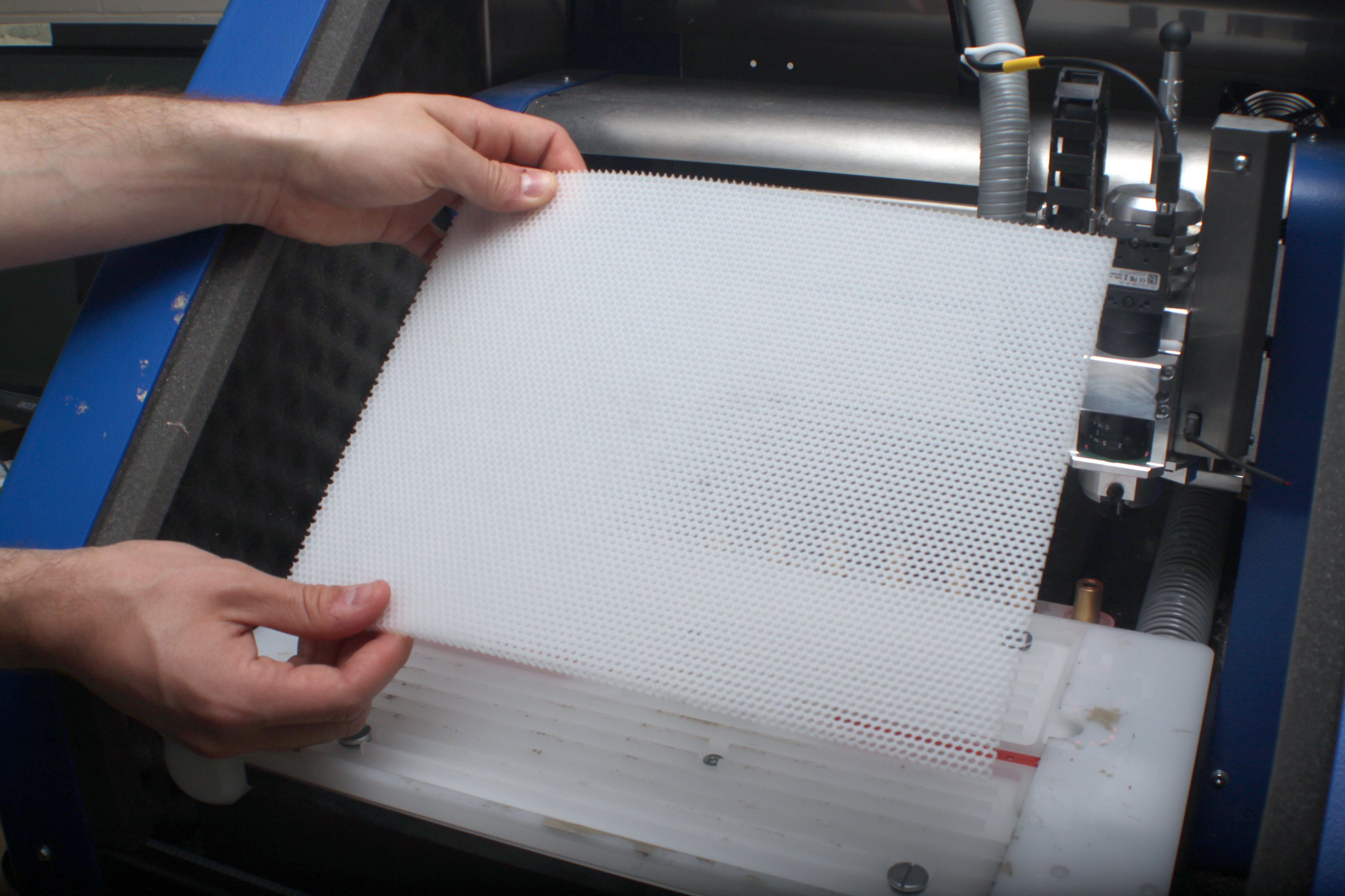
Get a sheet of felt-cloth and carefully place it on top of the honeycomb tray. The felt is often re-used many times and becomes stained with solder paste. This won't have any negative effect. You may use a stained felt-cloth, as long as it is is not in exceptionally poor condition.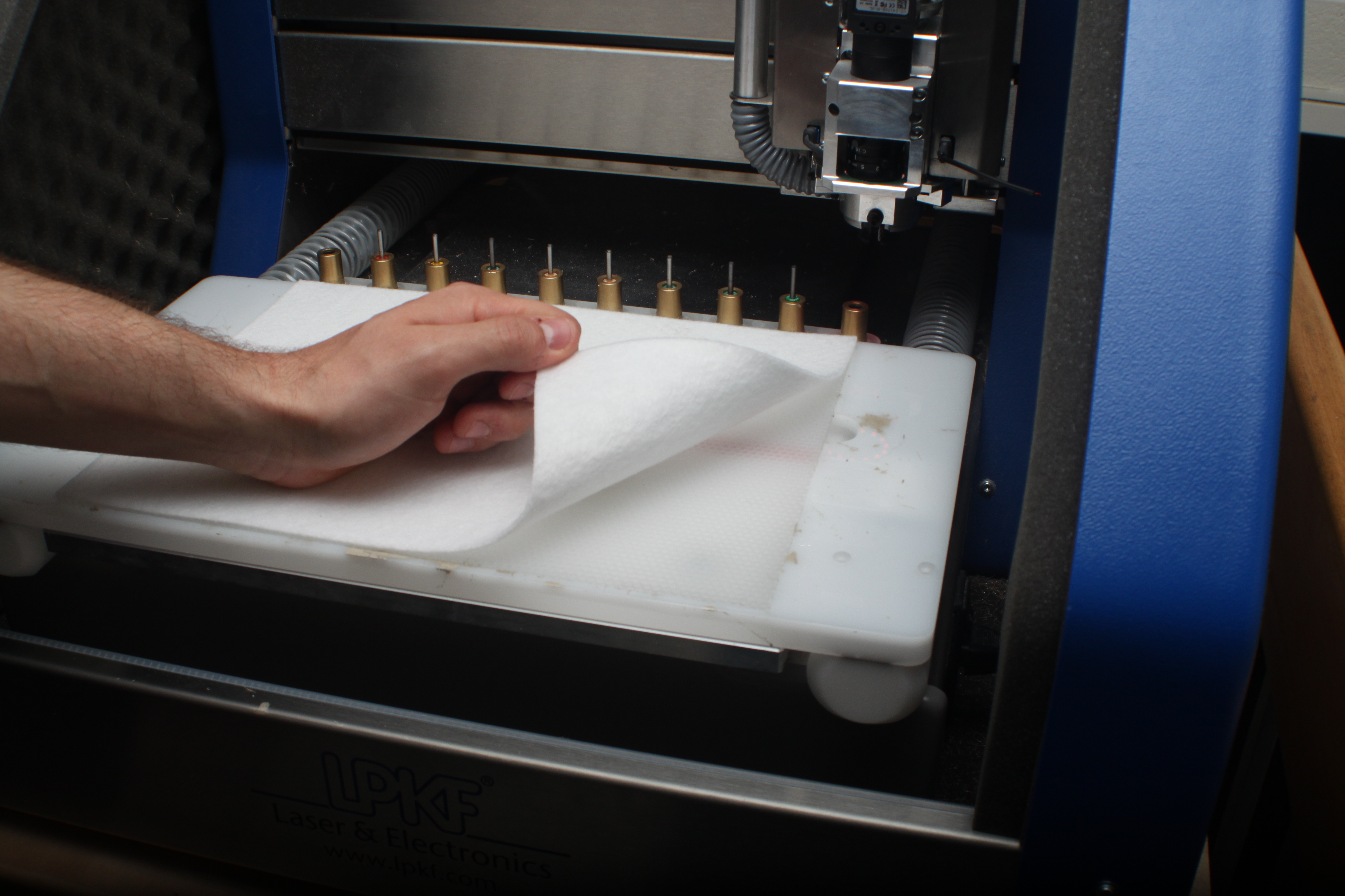
Next, lay-down a thin film of clear plastic on top of the felt-cloth. You need a cutout in the center of the clear plastic , whose dimensions are about 1/2-inch less than the circuit board you will place on top of it (the circuit board should completely cover the cutout part of the plastic when placed on top).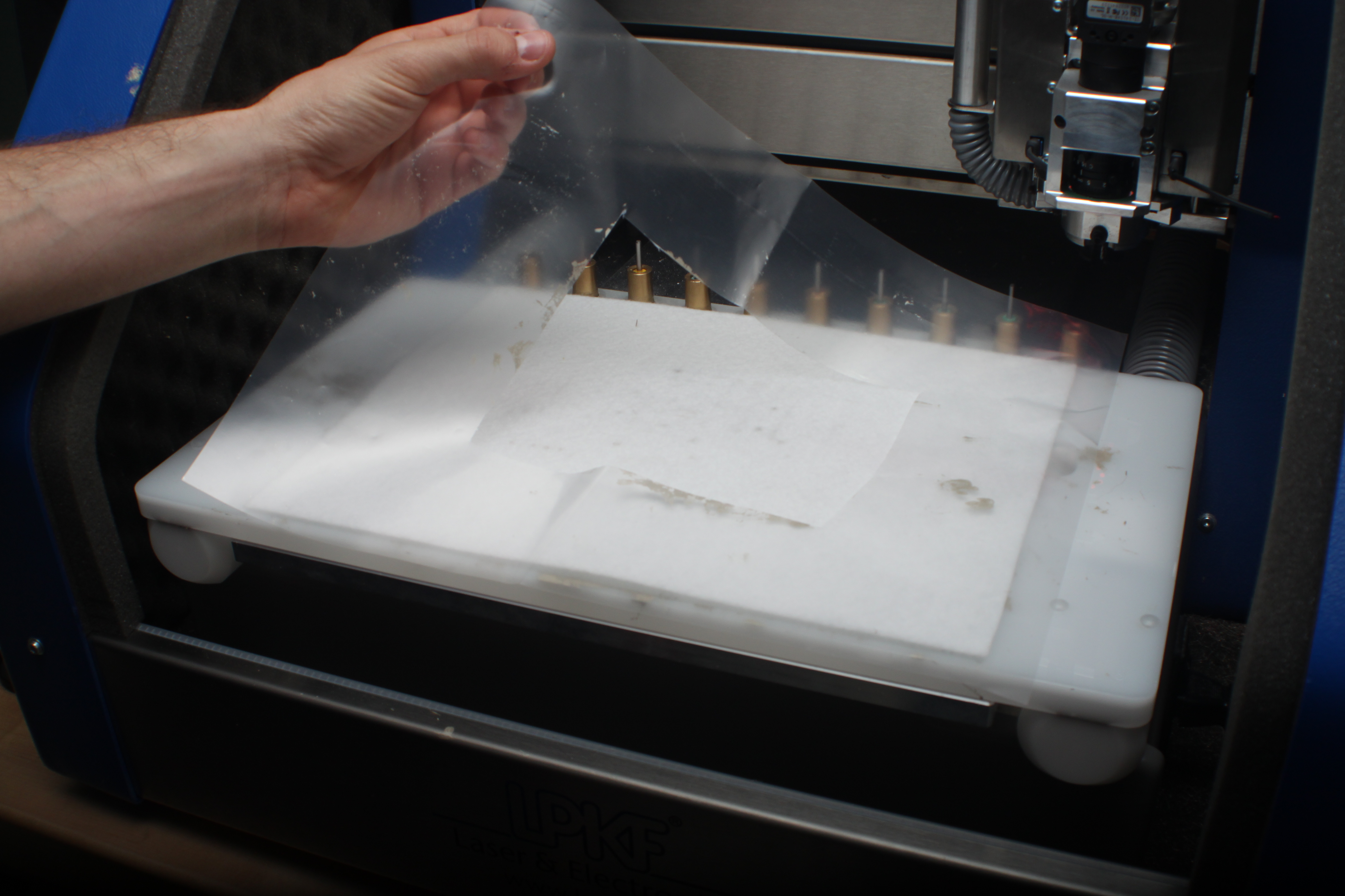
Place the circuit board on top of the plastic, completely covering the cutout. Turn on the vacuum system. This should create a strong net downward force on the board, fixing it securely in place.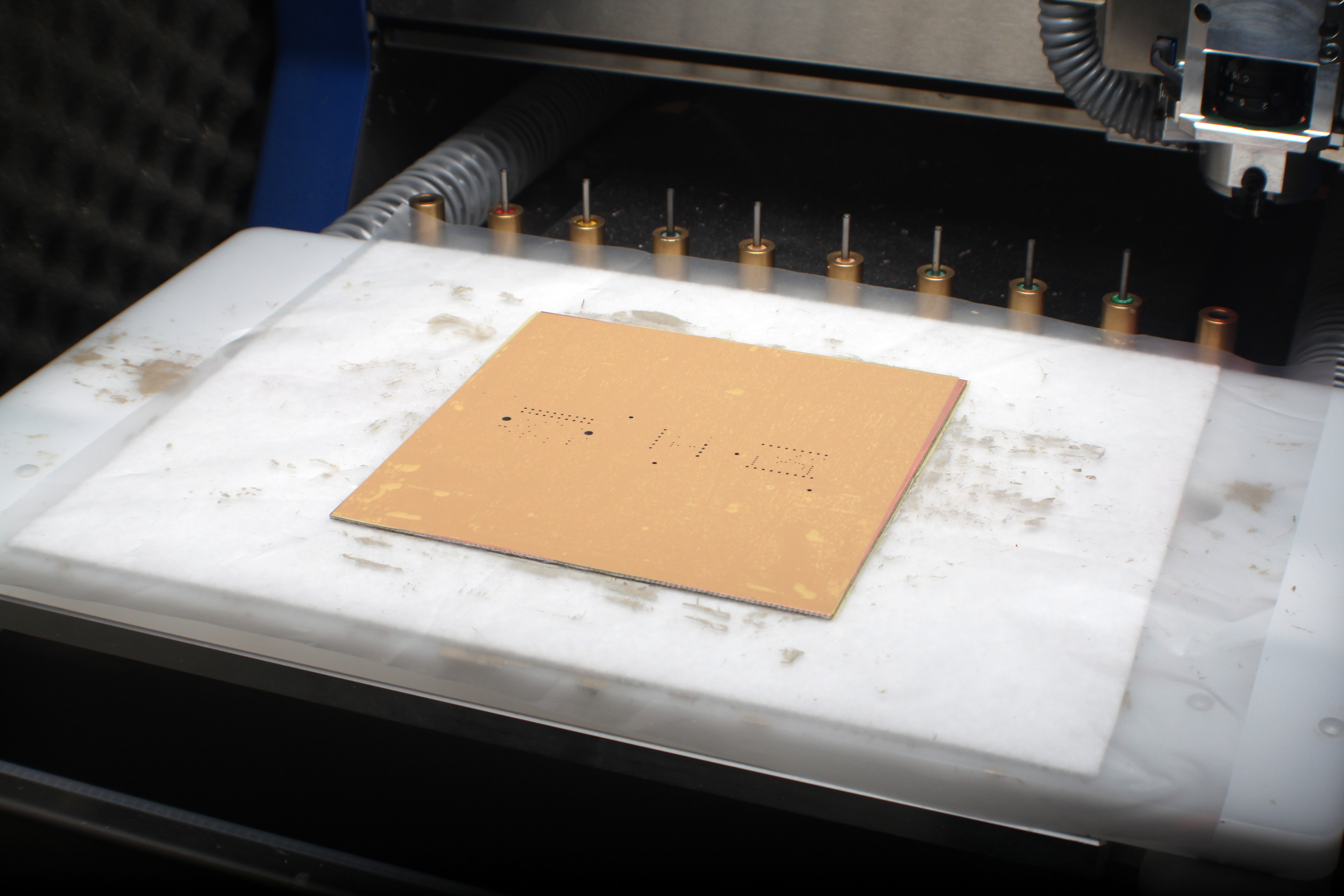
Get a small packet of solder paste. Squeeze and massage the packet of solder for 20 seconds, to warm it up. 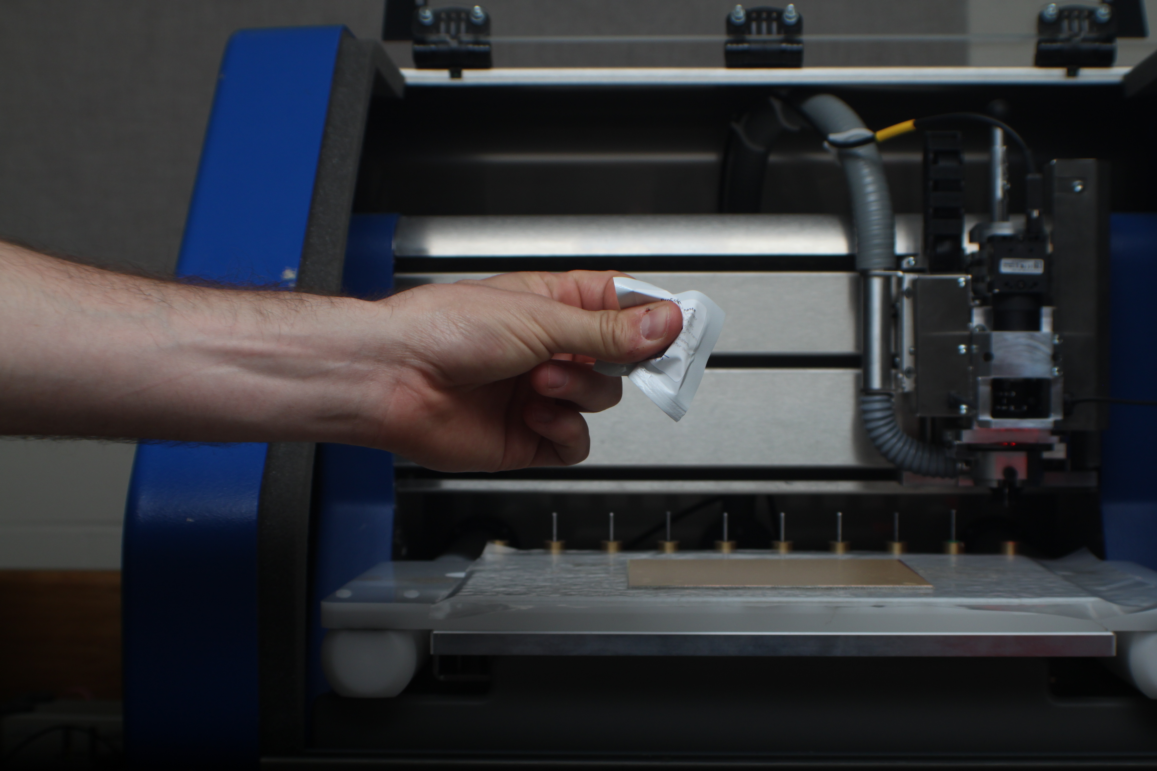
Get the rubber spatula. This will be used to spread the solder paste. Don't worry if it is badly stained - this will not affect your board.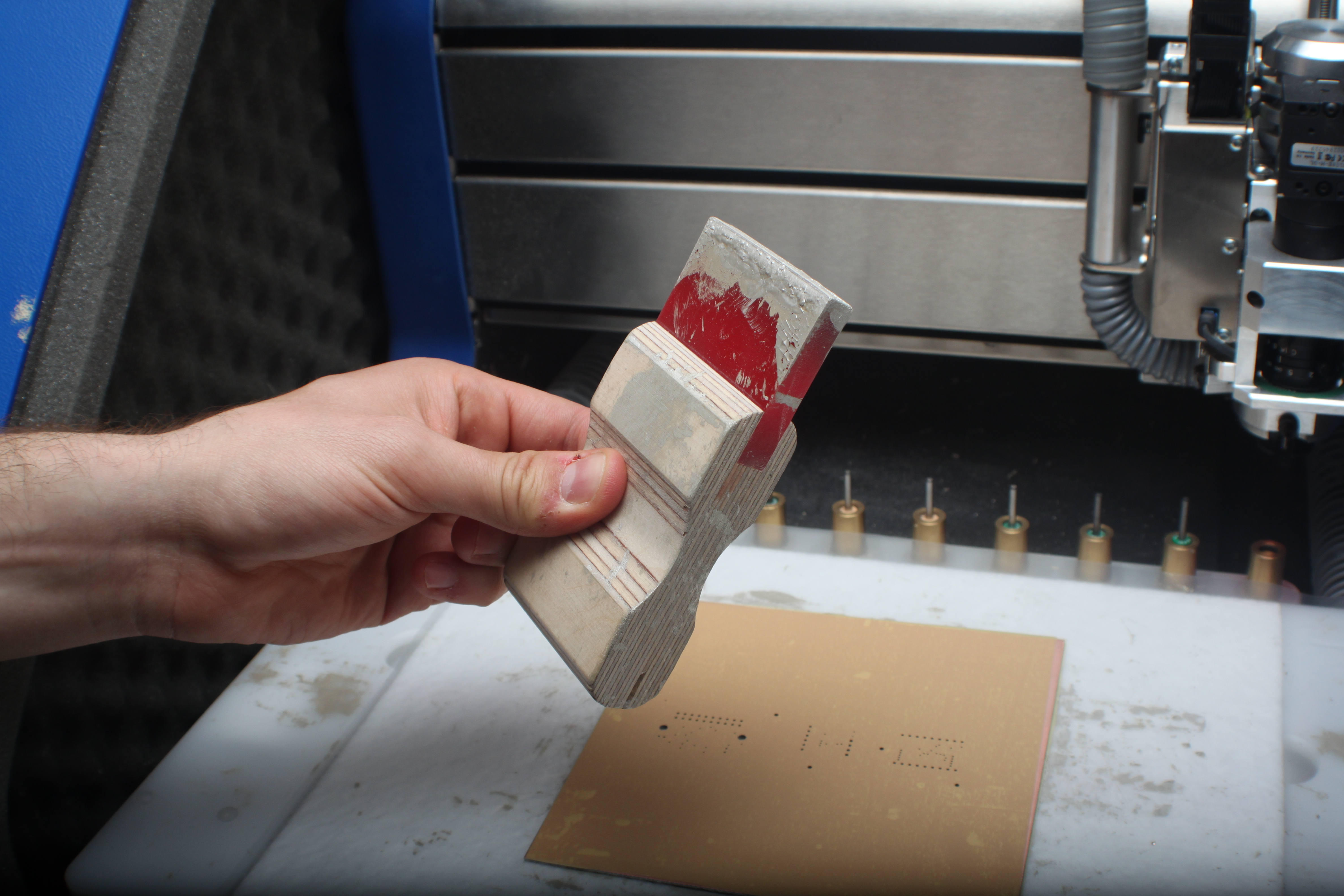
Open the packet of solder paste and pour about half of its contents on the surface of the circuit board, as shown below.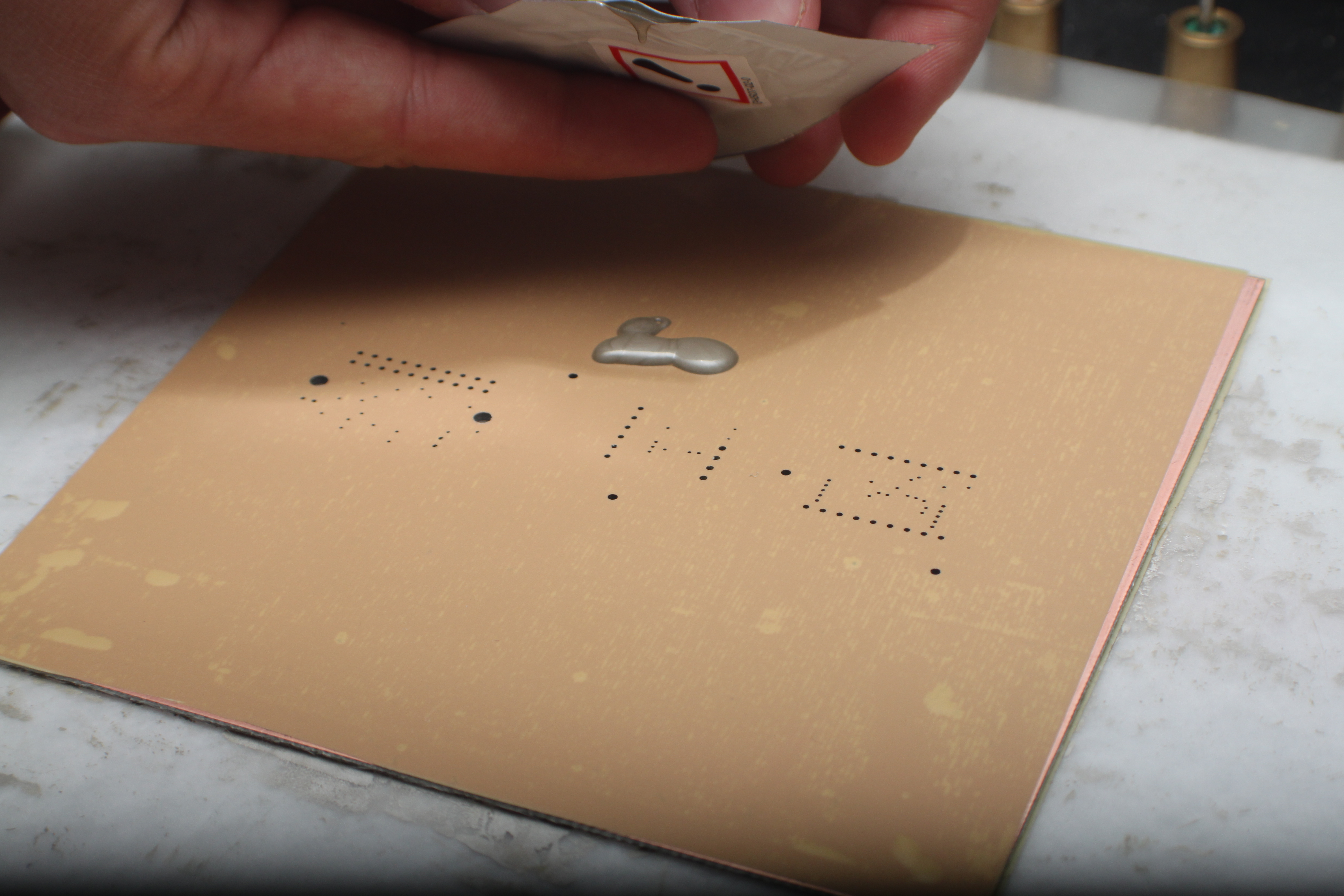
Use the rubber spatula to rigorously spread the paste across the surface of your circuit board. Ensure that the paste covers most of the board, so that a sufficient amount of paste is sucked into each of the holes. Work quickly, so that the paste does not dry or harden. Once it hardens, it cannot be spread very easily across the surface. After most of the paste has been used up (sucked into the holes), flip the circuit board over, and repeat on the other side.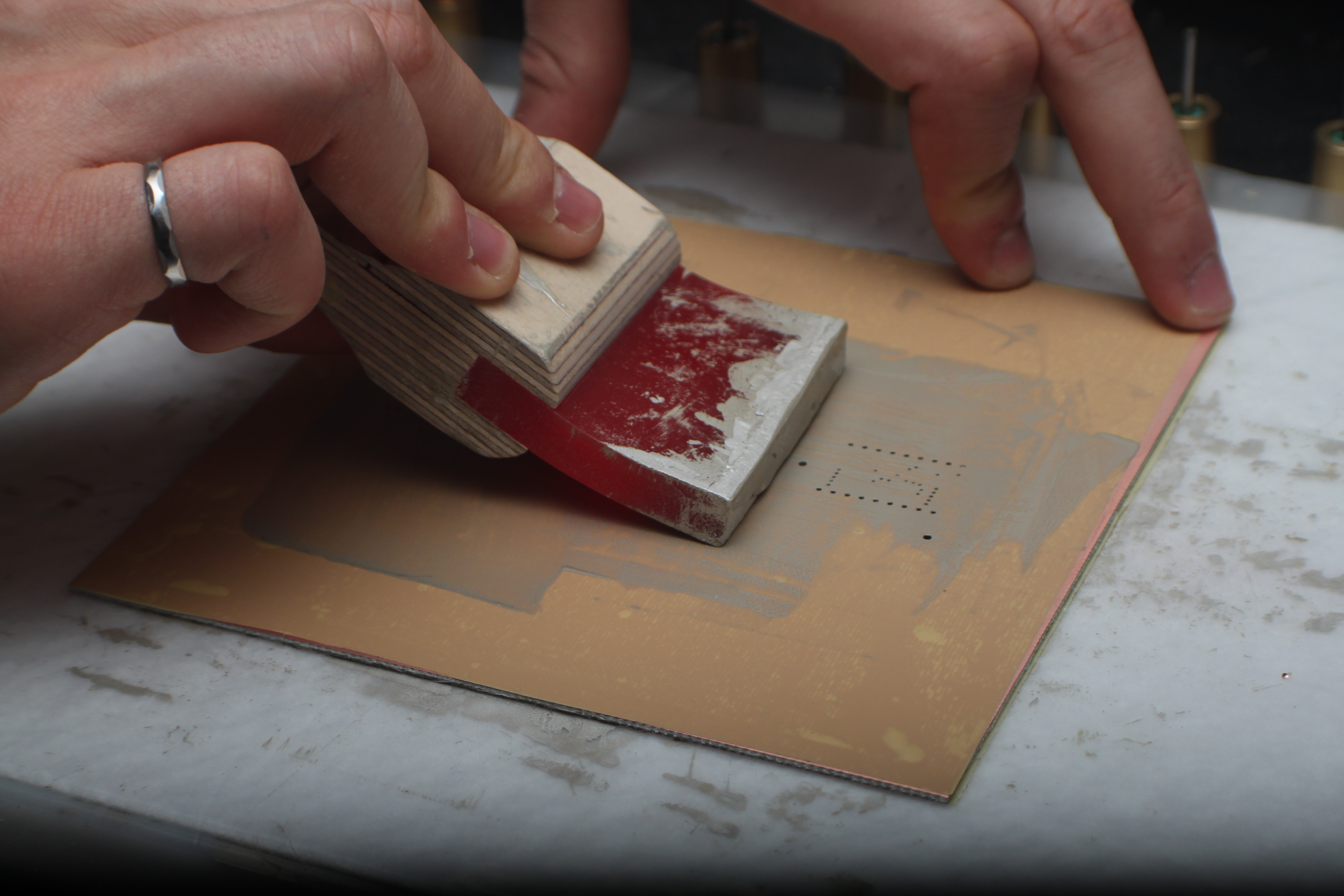
Once both sides have been given a generous amount of solder paste, and you are confident the holes each received some solder, you may turn off the vacuum system. Begin to peel off the sticker.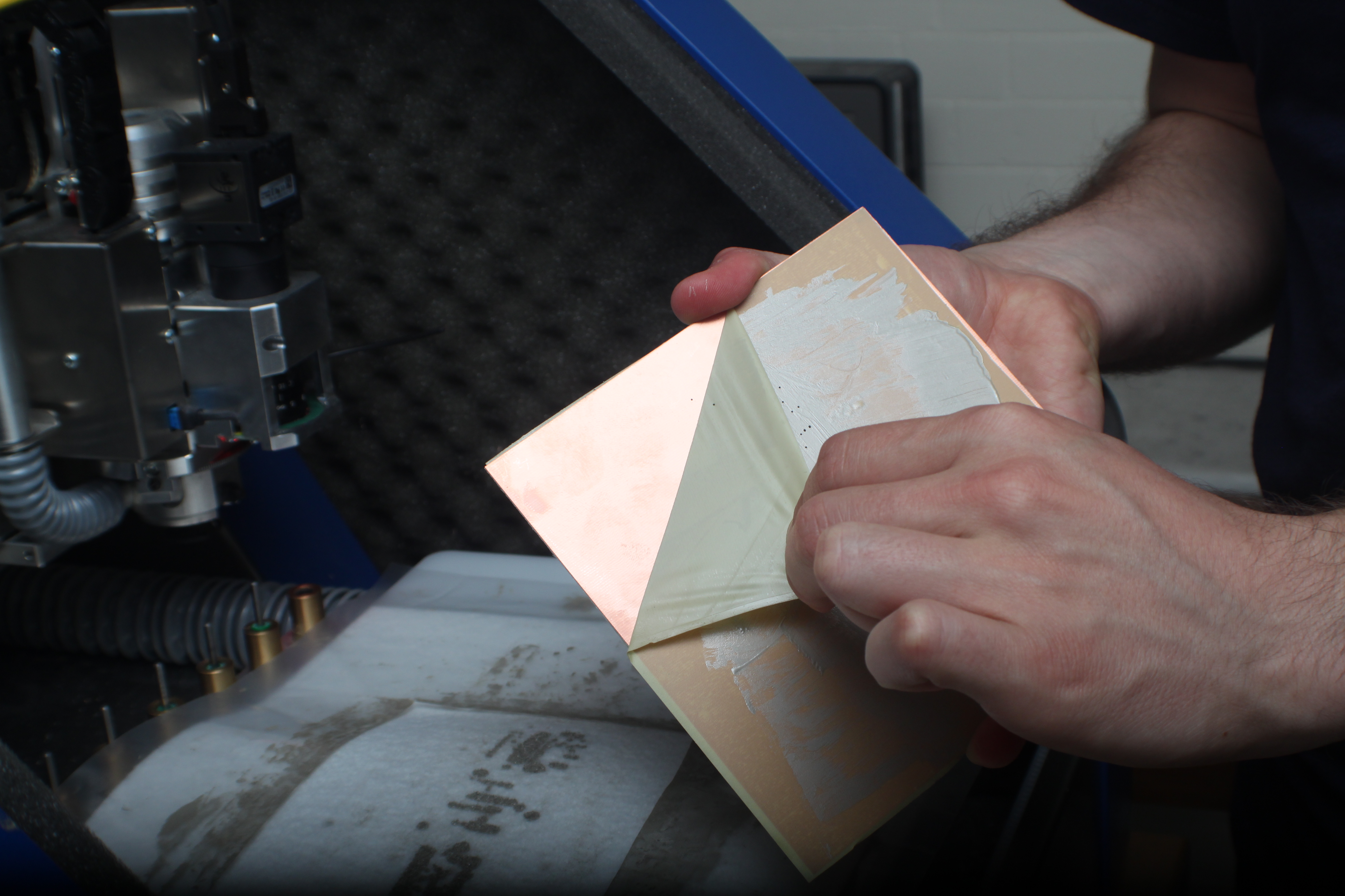
Repeat for the other side.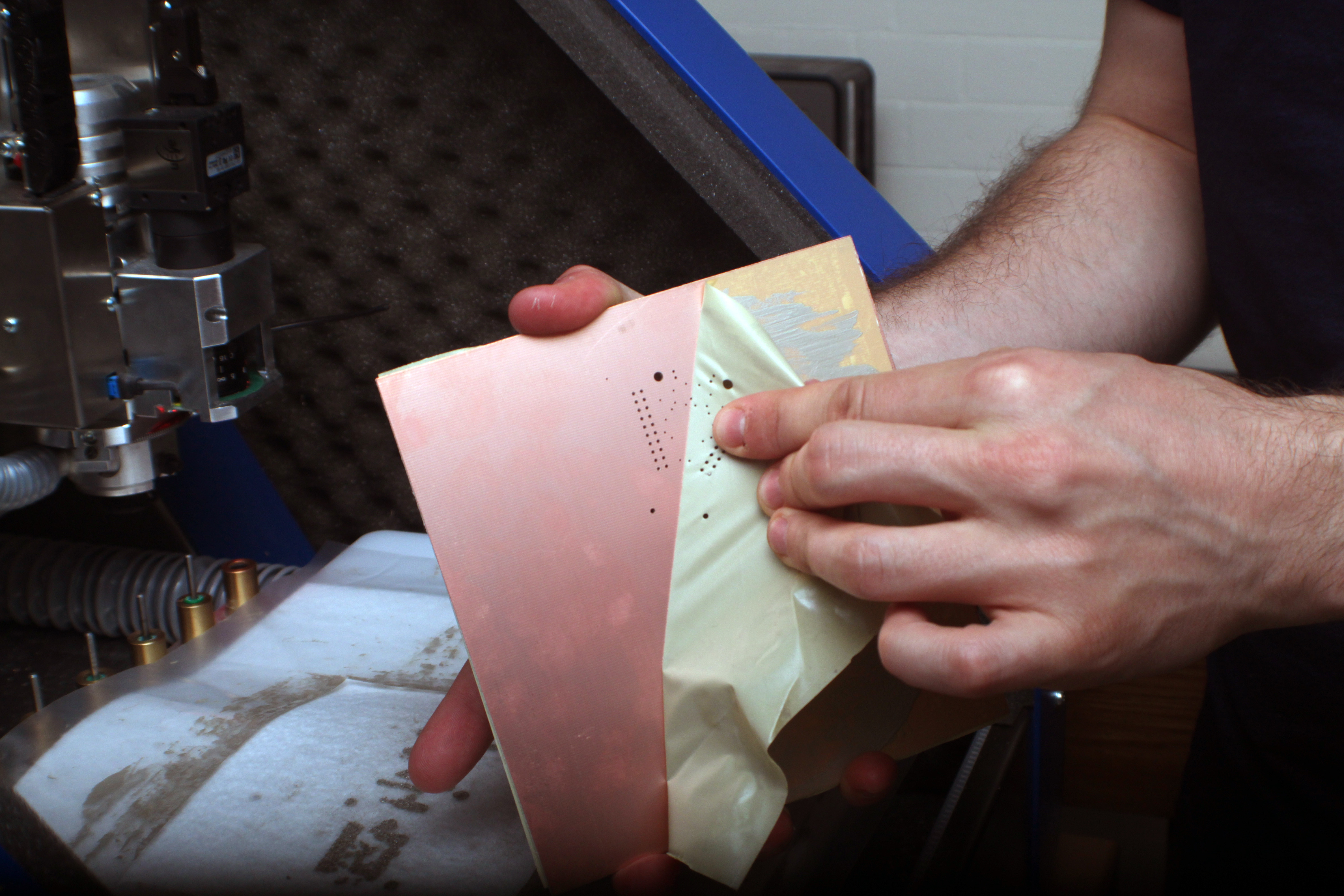
The oven should still be relatively hot from preheating. Set the timer to 30 minutes.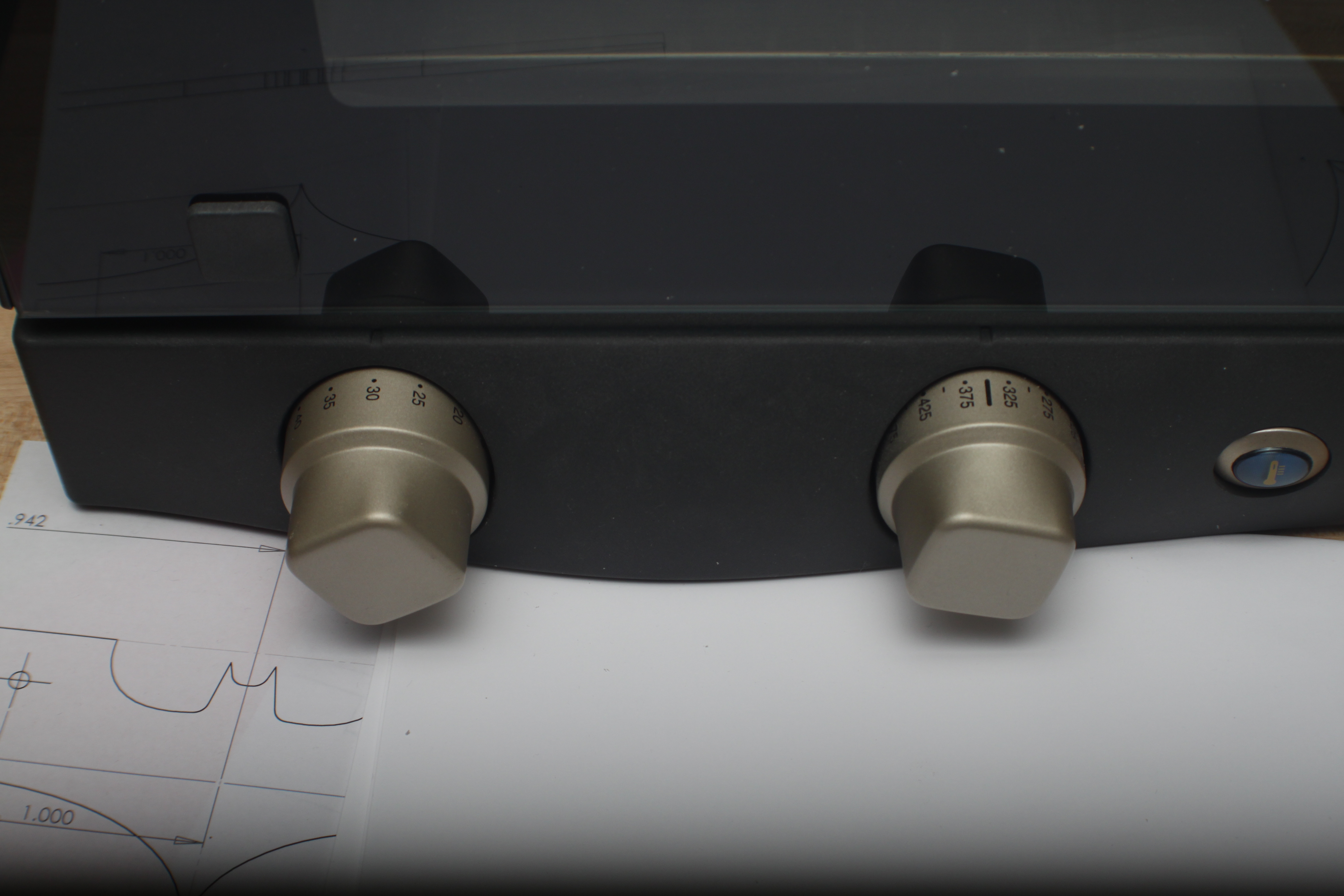
Carefully place your board in the center of the middle rack of the oven, and wait until the timer has reached zero. Once complete, removed the board and allow it to cool for 10 - 15 minutes before handling it or proceeding to the next steps.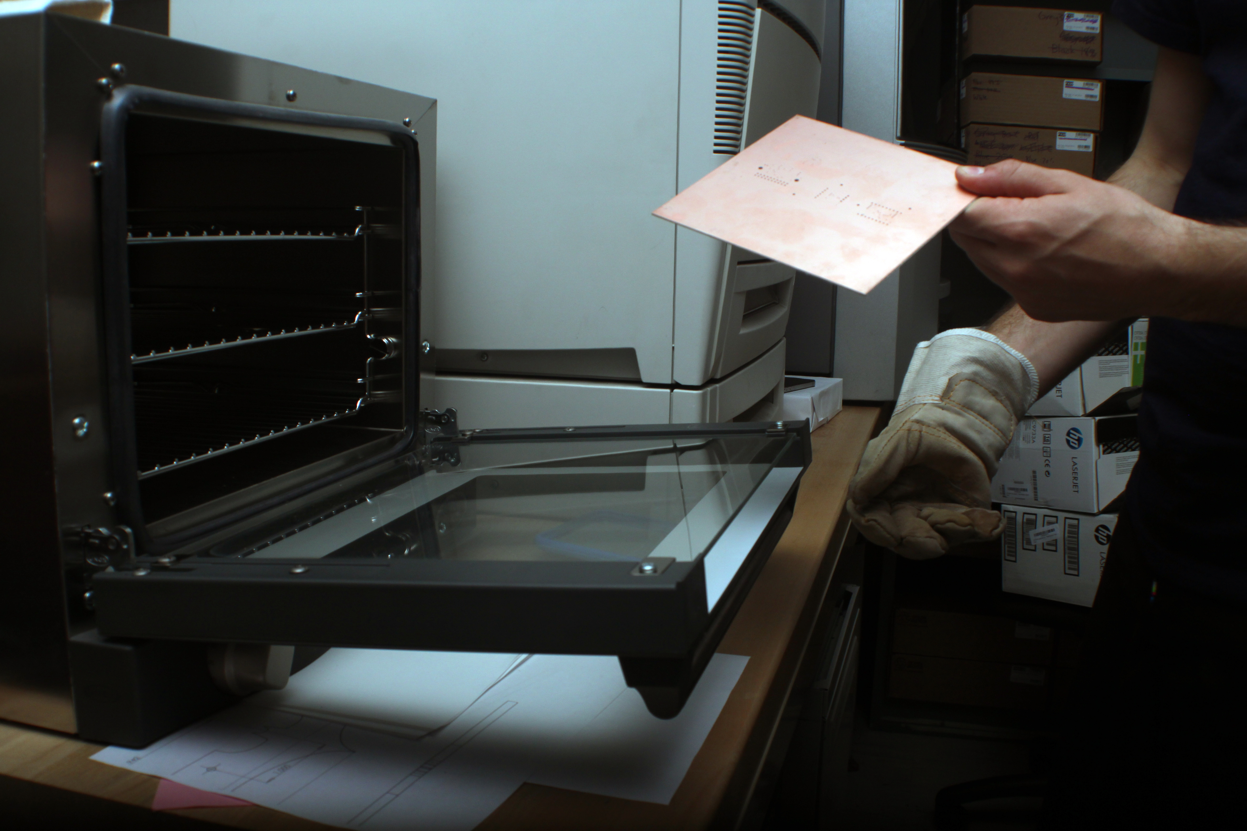
You are now done the through-hole plating process.\\