MEAM.Design - Laser Cutting - DraftSight
Preparing .DWG Files in DraftSight
- OPEN your .DWG file in DraftSight (Available in most MEAM labs).
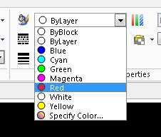
- To set how the laser will treat your geometry, you need to change the line colors. Do this by selecting a line, then choosing a color from the drop-down menu in the toolbar. Note that everything that is the same color will be treated similarly by the laser cutter (including the WHITE border � i.e. don�t leave your parts white!). The standard colors are:
- RED � vector cutting (lines that you want to cut all the way though)
- YELLOW � vector etching (lines that should be etched into your part)
- GREEN � raster etching (areas that should be etched into your part)
- CYAN � bounding box (lines to help position your stock, but won�t be cut)
- Once done, select all lines and define their line thickness as 0.05mm.
Defining Raster Etch Areas 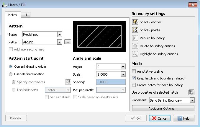
- Go to the Draw tab, and select Hatch/Fill.
- Select the Pattern drop-down box and change it to SOLID.
- In the Boundary Settings section, click Specify Entities. The Draw Hatch dialogue box will disappear.
- You will need to click and drag to select all entities that bound hatched regions.
- After you have selected all entities, hit Enter and the Hatch/Fill dialogue box will reappear.
- Be careful, the color of the geometries used to define the hatch will persist after the hatching process. If these are red, the geometries will be cut through. To outline your hatch, make these lines yellow, otherwise make green.
- Click OK and admire your hatched geometry.
- One last step - to change the color to GREEN, click and drag the mouse over your hatched area to select it, then change the color drop-down.