MEAM.Design - SAAST - A4: Introduction to the m2 and mX
To be completed by Friday, July 10th, this exercise should familiarize you with the m2 microcontroller, the mX expansion board, a handful of the subsystems, and the development environment that we will be using to to write and debug code. Keep an electronic copy of your answers to the questions in bold and submit them via this Google Form when you are finished.
PART 0: WARM UP
0.1 Reading
Read through the documentation for the m2 microcontroller and mX expansion module found on the SAAST homepage.
0.2 Pseudocode
(note - you will not be graded on the correctness of the answers in this section, so please do not modify these answers based upon your experience during the assignment.)
0.2.1 - Write pseudocode for part 2.1.
0.2.2 - Write pseudocode for part 2.4.
0.2.3 - Write pseudocode for your line follower (part 3).
PART 1: PROJECT SETUP
To develop and download code to the microcontroller, you'll want to follow the process outlined here, and copied below.
1.1 Create a new AtmelStudio project
Option 1: Creating a new project in AtmelStudio 6
2. Click on New Project
3. Select GCC C Executable Project, give your project a name, set the Location, then click Ok
4. Set the device to ATMEGA32U4 and click Ok
5. Within AtmelStudio, build the project (F7, or Build from the Build menu)
Option 2
For this option, you don't need to install AtmelStudio.
2. Place your source files (*.c) in atmega/src folder
3. Place your header files (*.h) in atmega/inc folder
4. Navigate command prompt (cmd) to atmega folder and execute:
make
[>-----Build Successfully-----<]
At this point, you should see the development environment with a blank file.
1.2 Install library
Download the latest library from the bottom of this page, as well as this starter code.
1.3 Upload code
Use the USB A-to-mini-B cable from your kit and proceed through the following steps to upload the starter code to the microcontroller:
2. click the button that looks like an IC, and select the ATMEGA32U4
3. plug in your microcontroller (if you haven't done so already)
4. hold the onboard button down for about two seconds (until the green LED turns on) then release (the orange LED should now be illuminated)
5. click the button that looks like a USB cable, select USB, then select Open
6. select Load Hex File from the File menu (the hex file usually lives in the default folder within your project folder)
7. click Run to upload your code to the micro
8. to run your code, press the onboard button for less two seconds (the orange LED should now be off)
PART 2: SUBSYSTEM TESTS
As you read about in Part 0, custom functions are available to control many of the subsystems of the m2 microcontroller. Keep copies of your (well-commented) code for each section, as you will need to upload each piece of code to the Google form.
2.1 Wait and LED Output
Use the m_wait() and m_red() functions to flash the red onboard LED at a frequency that you can see.
2.2 Digital Output
Modify your code from 2.1 to use the m_gpio_out() function to toggle the output of channel D7 instead of the LED. Adjust the wait time so that the output can be easily read with the multimeter, and verify that the output is changing accordingly.
2.3 Digital Input
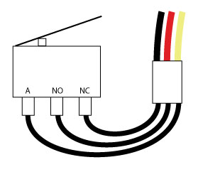
2.3.1 - Attach a SPDT limit switch to channel A on the mX board using a female-female three-wire cable and a few mini-grabber leads, as shown below:
2.3.2 - Program the green onboard LED to illuminate only when the button is pressed.
2.4 Analog Input
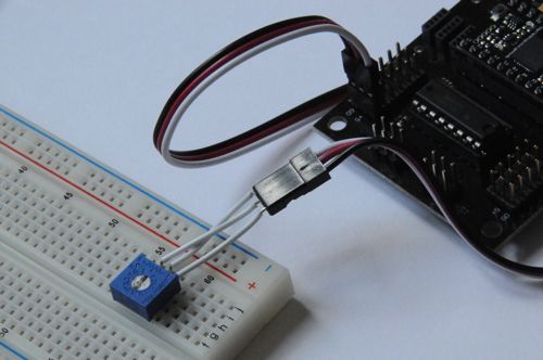
2.4.1 - Replace the switch with a potentiometer as shown below (where GND is at one end, 5V is at the other, and the input is connected to the wiper):
2.4.2 - Program the microcontroller such that the red LED will illuminate when the value is below 512, and the green LED will illuminate when the value is above 512, and test your code by adjusting the potentiometer throughout it's range.
2.5 Servo Output
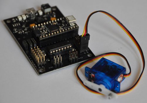
2.5.1 - Retrieve one of the micro servos from the box next to the ministore. With the potentiometer still connected to channel A, attach the servo motor to channel G. The ground line (usually black) should always be to the outside of the mX board. Double check the polarity before you plug it in!
2.5.2 - Program the microcontroller to have the servo motor follow the motion of the potentiometer.
2.6 DC Motor Output
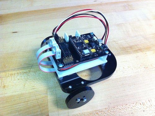
2.6.1 - Retrieve one of the Falhaber motors from the front of the lab. With the potentiometer still connected to channel A, attach the motor to channel 1 as shown in the robot photo in part 3 below.
2.6.2 - Program the microcontroller to have the motor rotate clockwise for analog input values less than 512 and counterclockwise for values greater than 512, with increasing speed the further away the reading is from the midpoint (i.e. - full CW at 0 and full CCW at 1023).
PART 3: LINE FOLLOWER
3.1 - Build an autonomous robot capable of following a line of dark tape on a light-colored background. You will be provided with the following components to start you off:
- (1) mX module with battery
- (2) Pololu motors
- (2) Pololu motor brackets
- (2) small wheels
- (2) wheel hubs
- (1) caster
- (1) acrylic body plate
- (1) acrylic spacer plate
- (1) pre-assembled IR line sensor
- (4) 3/8" 4-40 Phillips head screws
- (2) 1/2" 6-32 Phillips head screws
- (2) 3/8" Pan 6-32 Philips head screws
- (2) 1/2" 2-56 Phillips head screws
- (2) 2-56 nuts
Brief assembly instructions can be found here!
Hint: Think about using a potentiometer to quickly adjust the speed of your line follower!
3.2 Demonstrate your robot to a member of the teaching staff, record their name, and save off a copy of your code for the report.
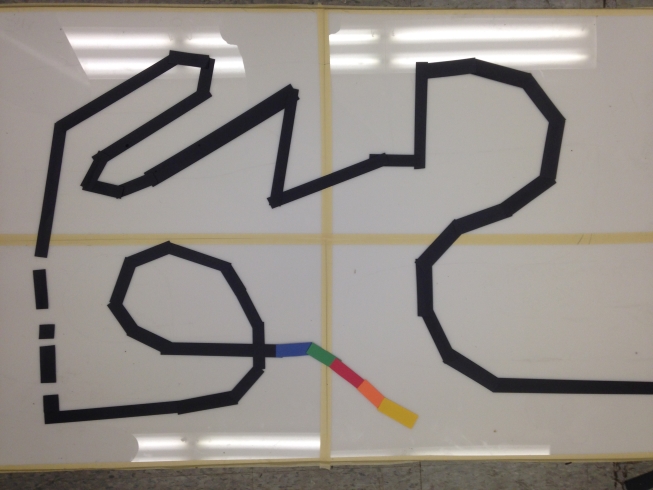
Line Follower Track:
SUBMISSION
Complete the questions and upload your code on the Google Form!