MEAM.Design - MEAM 410/510 - A1: Passive Circuit Analysis
1 Resistive Torture
Imagine you're working in the lab late at night, and desperately need a 600Ω resistor, but there are no discrete resistors of that size, and someone made off with all of the potentiometers. However, you do manage to find a small pile of 4-color-band resistors. There is one of each of the following: yellow-purple-brown-gold, brown-black-red-gold, red-red-red-silver, yellow-purple-red-gold, and brown-black-yellow-silver. Can you find a configuration of any/all of these resistors that will get you within 10Ω of your 600Ω goal? Realizing that no resistor is perfect, what are the maximum and minimum actual resistances for your configuration?
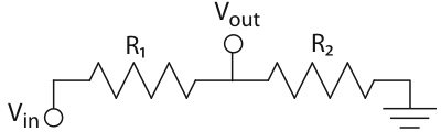
2 Voltage Division
What is the output voltage in the following circuit if Vin = 5V, R1=1kΩ and R2=470Ω? What would the output voltage be if a 1kΩ grounded load was attached to the output?
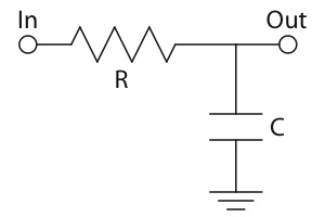
3 Low-Pass
A switch connecting a power supply to the input tof a first-order low-pass filter is instantaneously closed. How long, in terms of R and C, will it take before the output reaches 90% of the input?
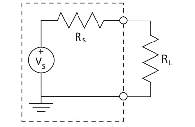
4 Impedance Matching
You have a voltage source, VS, with an output resistance of RS, and need to figure out how much internal resistance your load should have. Show that to achieve maximum power transfer, you should match the impedance of the load to the output impedance of the supply.
5 R_Battery?
In Lab 1 you measured the open circuit voltage of a battery and attempted to directly measure its resistance. One simplistic model for a real battery is an ideal voltage source in series with an ideal resistor. Describe a method for experimentally determining this internal resistance, given only a voltage meter and some resistors. A circuit diagram and equations will help your explanation.
6 Solenoid Troubles
(required for 510, e.c. for 410)
You've built an amazing little robot with a 24V, 6Ω solenoid to drive a kicking mechanism. However, the remainder of your robot runs on a 5V supply, and you've realized that at 5V the solenoid is pitifully weak. Is your kicker a waste? (Note: this is a rhetorical question that doesn't require an answer at this time.)
6.1 - Do some research into all of the possible ways to drive your fancy new solenoid. There is one relatively trivial answer. One rather-complicated answer. And one answer involves a Big Fat Capacitor (BFC). And there are probably other answers as well. Explain your methods in enough detail to convince us that they will work.
Given that we are working on passive components at the moment, it's time to dig a bit deeper into the BFC solution.
6.2 - You've set a requirement to achieve a total of at least ten 40-millisecond shots before the cap depletes from 24V to 12V (below which point it is too weak to be useful). To make this work, you've connected the ground side of the capacitor to one of the leads of the solenoid, and you have an ideal device that can connect and disconnect the positive side of the capacitor to the other lead. What is the minimum capacitance that you will need to meet these requirements?
6.3 - But how much will this fancy capacitor set you back? Browsing the major electronic-component distributor websites (www.digikey.com, www.mouser.com, etc.), find a reasonably inexpensive (less than $10) option to achieve this capacitance on your robot. Include a link to the item(s), the total price, and any details that you deem relevant.
6.4 - Finally, determine how you will charge your capacitor as quickly as possible given a 3A, 30V adjustable power supply from the lab. Note that you must not overload the power supply at any time. List all details of you charging scheme, include links to items, the total price of your solution, and any details that you deem relevant. Lastly, calculate how long it will take to charge the capacitor from 12V to 24V.