MEAM.Design - MEAM 410/510 - A3: Op Amp Magic
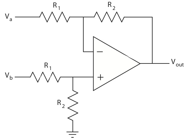
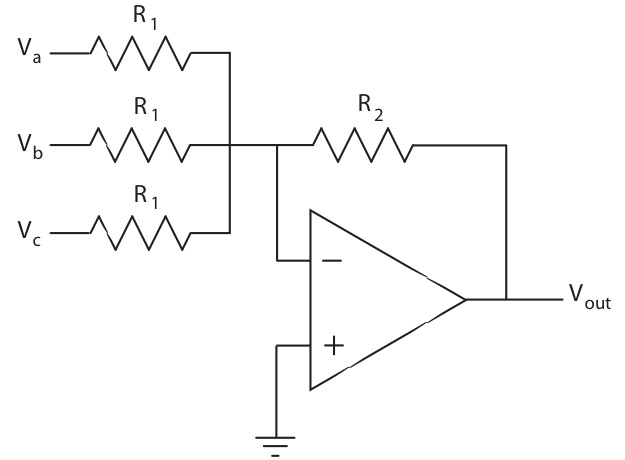
1 Op amp math
Beginning from the golden rules, derive the relationships between the output voltage and the input voltages for the following circuits:
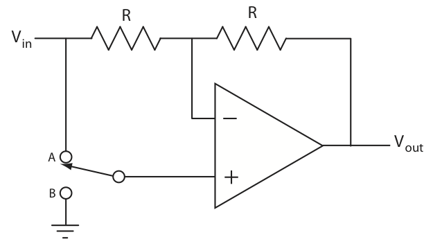
2 With a switch
Derive the relationship between the input and output voltage for each of the switch positions in the circuit shown below:
3 Trans-resistance
(this echoes problem 11.4 in the text)
Design a trans-resistive amplifier for a photo-transistor such that the circuit will have an output of 2.5V with no light falling on the sensor and an output voltage that rises with increasing light levels. You have a unipolar +5V supply, but you may assume ideal op-amps. Show a schematic and write the expression relating photo-transistor current to output voltage.
4 The non-inverting summer
In problem 1 you analyzed a circuit that was designed to add multiple analog signals together, but you may have noticed that it also inverts the signal (or, if you didn't, now you will). While you could add a second inverting op-amp stage to bring this back into the positive domain, there are times when this is not possible (for instance, when you have a unipolar supply). Can you design a circuit to use a single op amp and a unipolar supply to add two signals together without inverting the result? Please try to do this without looking it up on the internet, in a book, etc. If you absolutely cannot resist the temptation, you must cite any sources that you use.
5 Can an op amp do your calculus homework?
Using an ideal op amp, a resistor, and a capacitor, design (a) a circuit wherein the output voltage is the integral of the input signal, and (b) a circuit wherein the output voltage is the derivative of the input signal (edit on Sep 21: do not worry if the result is inverted, as I know you know how to add a simple inverting stage after the result). As I know that 90% of you will look this up on the internet, you must cite any sources you use, and you must show, using the golden rules and basic circuit analysis, why your circuits are correct. But even better, try to figure it out on your own first!
(Note: the following are not Op-Amp questions, though they want to be)
6 Stay Low (For a Little While)!
A 5V digital input signal to your circuit is originally high. It goes low. Between 15 and 30 milliseconds after going low, there is a short, 25-35ms pulse back high, then it returns low. You need to eliminate the high pulse such that once the signal goes low, it stays low for at least 100ms. Note that the transition from high to low must occur with a minimum of delay. Design a circuit to do this using components found in the GM-lab ministore.
7 Three Sensors
You have three sensors with 5V digital outputs. Call them A, B, and C. You need to drive two digital outputs, call them 1 and 2. Design a circuit using ministore-available logic gates that obeys the following conditions:
- When C is low, 1 and 2 will both be low, regardless of the state of A and B.
- When C is high and A is low and B is high, 1 will be high and 2 will be low.
- When C is high and A is high and B is low, 1 and 2 will both be high.
- When C is high and both A and B are low, 1 and 2 should both be low.