MEAM.Design - MEAM 247 - P2P1: Uniaxial Loading - Background
Tensile Loading
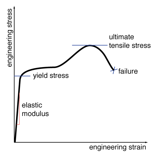
Plotting the engineering strain (change in length divided by original length) versus the engineering stress (applied force divided by the original cross-sectional area) in a sample can provide many insights into the material properties. A representative stress-strain plot for a tensile-loading case is shown to the right. NOTE: This plot is representative and is NOT drawn to scale.
Examining the curve at small strain values, we find that the relationship between stress and strain is nearly linear, and we take the slope of the curve in this region to be the elastic (or Young's) modulus.
As the load on the specimen is increased, the stress-versus-strain relationship becomes nonlinear, and further loading will result in plastic deformation. The point of transition between elastic (linear) and plastic (nonlinear) behavior is known as the yield point or yield stress.
Upon further loading, we reach the point of maximum engineering stress which is known as the ultimate tensile stress or UTS.
Most brittle materials (such as cast iron, acrylic, and most ceramics) exhibit little-to-no plastic deformation before failure, and as such their yield point, ultimate tensile stress, and failure point are often coincident.
Compressive Loading
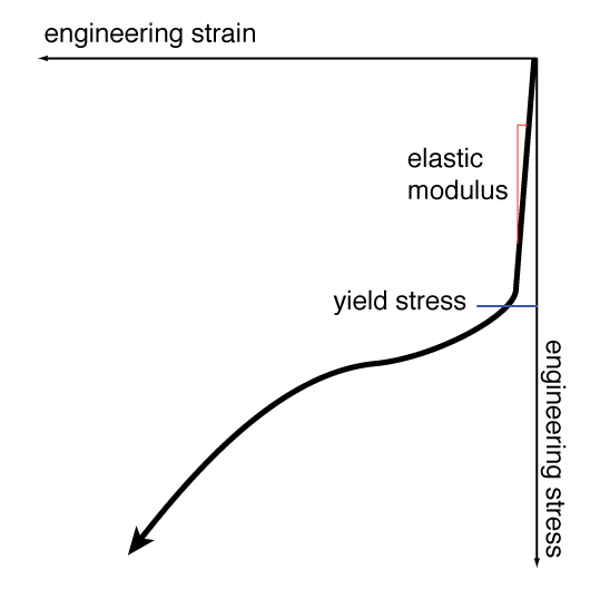
A representative stress-strain plot for a specimen loaded in compression is shown to the right. Once again, these are engineering stress and engineering strain. NOTE: This plot is representative and is NOT drawn to scale.
Examining the curve at small strain values, we find that there exists a linear relationship between stress and strain, the slope of which should match the elastic (or Young's) modulus found during tensile loading.
As the load on the specimen is increased, the stress-versus-strain relationship becomes nonlinear, and further loading will result in plastic deformation. The point of transition between elastic (linear) and plastic (nonlinear) behavior is know as the compressive yield point or compressive yield stress.
Under compressive loading, the maximum stress, or ultimate compressive stress, will always be experienced at the point of failure, due in part to an effect known as packing, wherein compressive forces will close cracks which would induce failure during tensile loading. This packing effect also allows many materials to withstand significantly higher loads in compression.
When the compressive specimen is relatively ductile, the Poisson effect causes the cross-sectional area to increase under load (the inverse of necking found in ductile tensile specimens), and as the specimen slowly flattens out it can be difficult to quantify the point of failure. In contrast, brittle materials often have a specific compressive fracture point at which the material splits.
It is important to note that slender specimens (typically defined as a length-to-diameter ratio of more than than 3:1) will often buckle before reaching compressive failure.
Behavior of Metals
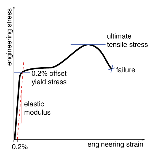
The curve shown to the right is common for many metals.
Elastic Modulus - At small strain values, the relationship between stress and strain is quite linear, making the estimation of the elastic modulus relatively easy.
Yield Point - Many metals lack a sharp yield point (i.e. a sudden, observable transition between elastic and plastic deformation), and as a result the yield point is defined empirically as the stress that corresponds to 0.2% permanent plastic strain. This value can be determined graphically by finding the intersection of the stress-strain curve with a line of slope equal to the elastic modulus passing through the strain axis at 0.2% (or 0.002 in/in).
Ultimate Tensile Stress (UTS) - By examination of the stress-strain plot, this is simply the maximum engineering stress which the material could withstand.
Behavior of Polymers
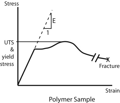
The stress-strain curve for a polymer (such as polyethylene or nylon) differs from that of a metal in both shape and magnitude. The most noticeable difference is that polymers typically reach strain values that are orders of magnitude higher than most metals due to a process known as "drawing".
Elastic Modulus - The elastic modulus for a polymer is found in exactly the same manner as it is for a metal (measuring the slope of the stress-strain curve for small strains), although it is important to recognize that some polymers can exhibit significant nonlinear behavior in the elastic region.
Yield Point and Ultimate Tensile Stress - By definition, the yield point and ultimate tensile stress for polymers are defined as the maximum engineering stress achieved by the material.
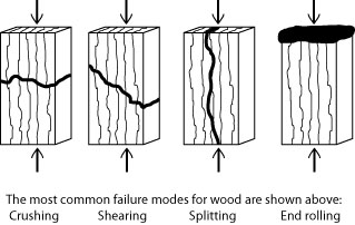
Anisotropic Materials
While most of the materials that we will study will be isotropic (uniform properties in all directions), there are many materials wherein the properties differ by direction. Some natural materials (e.g. wood) and many of today�s engineered composites (e.g. carbon fiber) are anisotropic. In wood, which is composed of long slender packets of cellulose enclosed by void areas, the long, fibrous nature of the grain leads to very pronounced anisotropic behavior. The image to the right depicts four different failure modes for a typical wooden specimen loaded along the grain.