Autonomous Microrobotic Path Planning for Single Cell Manipulation
I. Abstract
This ongoing collaboration between the GRASP and Biology Labs at the University of Pennsylvania focuses on the targeted delivery of chemicals to cells using microscopic robots. There are many applications of single cell manipulation in biology, pharmacology, physiology and other related fields. Generally, these types of applications are completed through teleoperation of a microscope bed by a human. The general goal of the overall project is to navigate to single cells with micron-size precision, and deliver a bead of chemical without disturbing the local environment [1]. For the sake of this class, the short-term project goal is to begin an infrastructure to allow the micro-robot to complete its task autonomously.
II. Introduction and Background
In order to write a path planning algorithm that the robot will be able to follow, it is important to understand the nature of its movement and its task. However, only a brief description of the physics will be discussed; instead focus will be on how the physics effects the approach to the task.
i. The Robot
The robot is truly nothing more than a piece of metal that is micro-fabricated to have a specific size and shape. The robot is then magnetized using a high-power magnet in such a way that the magnetization vector points out of the opening of the U shape[1], as can be seen in figure 1.

Figure 1. The microscopic robots, on the scale of 30x30 micrometers, are used to move beads of chemical to a single cell.
These micro-robots are specifically designed to push beads of a particular size, and can be re-made to work with beads of any size. The main concept to note about the beads is that they must be pushed. That is, the physical connection between the micro-robot and the bead is not significant enough to ensure contact through turns of more than approximately 20 degrees. Also, any debris that is in the path can cause the bead to slip away.
ii. Robot Movement
The robot's movement is controlled through a hand-made array of electromagnetic coils that is placed in the microscope bed. The free-standing coil array can be seen in figure 2.

Figure 2. The electromagnetic coil that controls movement of the robot.
Energizing each coil produces a different movement in the micro-robot; they are currently controlled based on the robot's position. Specifically, if the robot is down and left from the desired position, the up and right coils will be energized. This will create a vector field in the direction of the target position WIKI. While diagonal movement is possible, it is most likely easier for the robot to move in the four cardinal directions. More about this will be discussed later in the next major section.
iii. The Environment
The environment is on the scale of 150x150 micrometers, while the bead (not shown yet in figures) is approximately 10 micrometers in diameter. The neurons shown in figure 3 are specifically rat hippocampal neurons, the main target for manipulation in the reference paper[1].

Figure 3. The environment is cluttered with cell nuclei and dendrites, making teleoperation navigation difficult.
In the current experimentation, a preprocessed binary image of five neurons and their major dendrites will be used to simulate these cells; more information about the vision can be found below.
III. Approach
Since the direction of movement was initially thought to be very restricted, the path planning was written in 4-connected space. However, after some tests with the actual robots, it was discovered that they are able to move in diagonals very well. Therefore, experimentation was done with both 4-connected and 8-connected space, focusing on 8-connected since the paths tend to be shorter.
i. Simplifying the Vision
Previous attempts at tracking the robot and bead were done from images similar to figures 1 and 3. While this infrastructure is still in place, this project made the tracking even simpler. With the current microscope, images can be made simpler by using the filtering in the microscope lens. Specific waves of light are filtered based on the type of material that the robot and bead are made out of. Since the camera is black and white, the image now has a dark background with dark gray objects; a simple binary threshold is used to filter the background from the micro-robot, bead and cell.

Figure 4. The threshold, binary image taken from the microscope.
The image in figure 4 is simulated from two images, one with the micro-robot and bead, the other with the rat hippocampal neurons. This is also the image that the current robot-tracking system uses, which tells the controller where the robot is and the direction that it is going.
From the image in figure 4, the robot and bead are removed and an OpenCV function called dilate is used to 'grow' the neurons, creating the configuration space shown in figure 5.

Figure 5. The configuration space for path planning.
The configuration is a defacto Minkowski sum image, in that the effect is the same as a calculated Minkowski sum, but uses a very simple OpenCV function.
ii. Autonomous Path Planning
The path planning needs two separate steps: one path from the robot starting area to the selected bead and one from the bead to the selected neuron. The A* path planning algorithm is done in pre-processing from a single feedback image from the microscope. Once the robot is in contact with the bead, it is important that its motion remains in a consistent direction so the bead does not slip away on its path to a neuron. Because of the fairly limited motions of the robot, it would be best to approach the bead from a direction opposite that of the desired site. Therefore, the algorithm ensures the robot is facing the correct direction on its second path from bead to cell.
The configuration space for each path is constructed so that the second path from bead to cell is as straight as possible. To ensure the robot approaches the bead from the correct direction, an artificial obstacle is constructed around the bead. A path is then carved out from the bead to open space along the direction of cell-to-bead translation. The A* algorithm is then run on this first configuration space. From there, a free path is carved out from bead-to-cell and the second A* completes the path. In all of the figures below, blue is the robot start, green is the bead position and red is the target location on the cell.

Figure 6. (a) Configuration space for start (blue) to bead (green); (b) the second configuration space from bead (green) to cell (red).

Figure 7. The completed A* path (yellow) from the configuration spaces shown in figure 6.
The example in figures 6 and 7 is using 4-connected space. As mentioned above, both 4-connected and 8-connected space can be used in this algorithm. Below are a few different completed paths using both can be seen in figure 8 and 9.

Figure 8. More examples with 4-n space.
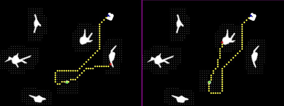
Figure 9. More examples with 8-n space.
The heuristic used for 4-connected space was Manhattan distance and for 8-connected it was Euclidean distance. From these paths, one in every four points is taken for the controller to follow. That way, the robot is still able to make any turns, but does not need to take in too many points.
IV. Experimentation Results
i. Experiment Process
For the scope of this project, the experimentation was done with just the micro-robots and the beads of chemicals. All of the cells were simulated to make for more interesting paths. Once the robot-bead mixture was under the microscope, it was important to find an area where the robots were not clumped too close together and there were many beads to choose from. This was not always an easy task and sometimes required 'guess-and-check' points to move the robot to a usable workspace. An extra, simple algorithm to move the robot to a specific place would have been useful. Once a good image was taken, a user is asked to click on the bead, robot and cell that the path planning algorithm will run on. Then, a separate function was used to control the electromagnetic coils and the movement of the micro-robot with the aforementioned methods. The video below shows three successful runs in the actual experiment environment.
http://www.youtube.com/watch?v=OTgSipjn15w
Video 1: Three successful paths.
As mentioned before, the five neurons in the video, shown in green, are simulated for the sake of the project. Everything in white are actual objects on the microscope slide, either debris or other usable beads. The path is planned to the bead indicated by the user.
V. Future Work
i. Expanding the Experiment
The current work has only been done with robots and beads under the microscope with simulated neurons. The next obvious step would be to add cells to the mix and see how their presence effects the physics of the experiment. Since the current experiment requires a lot of set-up time and human interaction to run the programs, a more automated system would reduce experiment time.
ii. Improving Path Planning
Multiple times during experimentation, the bead or robot would shift its position. If the robot moves, it is easy for it to still follow the predetermined path; if the bead moves then the experiment will fail. With the current setup, the A* algorithm is done using a single preprocessed image. A vast improvement to this method would be to have a dynamic A*, one that is constantly checking and improving its path. Since the bead can move dynamically, so should the robot's path.
iii. Improving the Controller
The current controller only uses feedback on the micro-robot's position, which can make the movements uneven. Upon closer review of the successful videos, it can be seen that the robot tends to jerk in one direction. A good fix to that problem would be to control via speed feedback as well as position. This also helps the fact that the robot's velocity tends to speed up while going in certain directions.
All microscope images are courtesy of Ed Steager.
References
[1]M. S. Sakar, E. B. Steager, A. Cowley, V. Kumar, and G. J. Pappas, 'Wireless Manipulation of Single Cells using Magnetic Microtransporters.', 2011 IEEE International Conference on Robotics and Automation.
Comments from Final Presentations
Anirudha Majumdar
Simple but interesting concept, but more info on the dynamics you used would be interesting to see. Also, is there a real world use for this concept?
Avik De
Good, clear presentation and explanations on a very theoretical project. Your figures made your presentation.
Ben Charrow
Cute video, even though the PR2 got alittle lost at the end. I like that you challenged yourself by pinching instead of an enclosed grip.
Brian MacAllister
Interesting view of a complex problem, I liked your simulation.
Caitlin Powers
You put alot of info into a short presentation, it was a good explanation but perhaps too much for a short time. I am interested to see you implementation on the arm.
Fei Miao
A very well thought out problem, you explained your challenges very well. The path created were not optimal, perhaps include an efficiency algorithm?
Jason Owens
Cool vision implementation, but you didn't explain the real world applications, i.e. detection in airports or the use of backpacks by robots (I am not sure which).
Kartik Mohta
This will be really cool if you can implement it with real quadrotors and get an overall image of a given space.
Menglong Zhu
Nice use of the PR2! However, can this be implemented with the same robustness on another robot with different hardware, say less expensive cameras?
Philip Dames
Good concept, but its hard to tell how good your implementation is since you were only using one robot. Continue pushing through!
Steve McGill
Cool implementation, but do the objects need to be specifically design for their detection, or are the Darwin camera not robust enough for more complex detection?