MEAM.Design - MEAM 410/510 - L1 (Stalker) - Part A: RC Filters
Lab 1, Part A: RC Filters
This exercise should familiarize you with some of the equipment in the GM lab in addition to some basic electronic components before taking you through an exercise in passive RC filters. While you can work together, it is vital that everyone form a personal understanding of these basic concepts! Concise answers to the questions in bold are to be submitted at the beginning of lecture.
1: METERS, SUPPLIES, SCOPES, ETC.
1.1 - The Digital Multimeter (DMM)
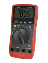
The GM lab tool crib has an assortment of digital multimeters for you to use. These are most commonly used for checking voltages or measuring resistance (though most of them have numerous other functions). Each multimeter should have two test leads attached to it (one red, one black). For the purpose of this lab, we will leave a number of multimeters in one of the open cabinets in the lab. Please wrap the test leads around your multimeter and return it to this area when you are finished.
1.1.1 - Inspect your multimeter. The black lead should be plugged into the hole labeled COM (which stands for common, often referred to as ground - as a convention, you should try to always use black colored wires for ground, it will make debugging complicated circuits much easier!). The red lead should be plugged into the hole labeled V/Ω. The multimeter is now set up to read voltage or measure resistance.
1.1.2 - Take a minute to familiarize yourself with the symbols on the multimeter dial.
1.1.3 - Find a battery. Measure the voltage across the terminals. Is the voltage what you expected it to be? Is there a measurable resistance across the battery terminals?
1.1.4 - Set your multimeter to connectivity testing mode (when set to test for connectivity, the multimeter will beep when the resistance between the two probes approaches zero, which can be quite useful when trying to find breaks in circuits that should be connected). See which parts of the bench or table are electrically connected.
1.2 - The Variable Power Supply
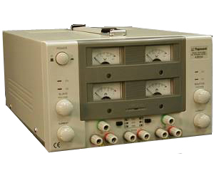
Most desktop power supplies allow the user to adjust the output voltage and/or current of multiple channels, with some type of display to indicate the output parameters. Some of the GM lab power supplies have two variable channels and a fixed 5V channel. Others just have one variable channel. The variable channel(s) can operate in either CV (Constant Voltage) or CC (Constant Current) mode, as indicated by the two LEDs. Only one light will be on at a time. When the CV light is illuminated, the power supply will maintain the output voltage set by the dial, thereby supplying as much current as required to maintain that voltage. Conversely, if the CC light is illuminated, the power supply has reached the current limit set by the current dial, and the voltage will decrease as needed to maintain the desired current.
1.2.1 - Turn on the power supply. If you have a dual-channel supply, ensure that the switches are set to independent (IND) mode. Turn the current knob for one of the channels all the way up (clockwise). Does the current display change as you do this? Why? Turn the voltage knob. Does the voltage display change as you do this? Why? Does anything happen to the CV and CC lights?
1.2.2 - Note that there are three output connections for each channel: ground, negative (-), and positive (+). Using the DMM, measure the voltage difference between the (-) and (+) outputs as you adjust the voltage knob. Do the multimeter and the power supply agree? Does the current display show any current? Now measure the voltage between the ground and positive terminals. See if you can explain the difference between the ground and negative terminals.
1.3 - The Oscilloscope
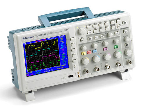
One of the most versatile instruments in the lab, an oscilloscope is a device for examining the time-dependent nature of signals. In addition to showing voltage versus time, the two-channel digital scopes in the GM lab can also measure many signal properties, including peak-to-peak amplitude, frequency, rise time, and duty cycle. It is important that you always use a dedicated scope probe when measuring signals, as the probes have internal circuitry which greatly improves the accuracy of your measurements.
NOTE: The probe tip has a short wire with an alligator clip sticking off the side - this is connected to ground within the scope. Attaching this clip to ground in your circuit will allow you to take ground-referenced voltage readings, but you should make sure that you do not accidentally ground part of a circuit by attaching this clip in the wrong location - BAD things can happen!
1.3.1 - Turn on the oscilloscope. While it is warming up, grab a banana-alligator cable and scope probe from the racks in the back of the lab. Connect the banana-alligator cable to the power supply, and the scope probe to the oscilloscope on CH 1. Connect the scope probe ground wire to the black alligator clip, and the scope tip to the red alligator clip. Ensure that the scope probe is set to x1 mode. Press the CH 1 MENU button and make sure that Coupling is set to DC and the Probe is set to 1X. Turn the VOLTS/DIV knob for CH 1 such that the text in the lower-left corner of the screen reads �CH1 5.00V�. Turn the SEC/DIV knob until the text in the lower-middle of the screen reads �M 250ms�. Now, turn the voltage knob on the power supply, and watch the oscilloscope screen...
1.3.2 - Using the same setup as above, set the power supply voltage to approximately 10V. Toggle the switch on the scope probe from x1 into x10 mode. What happened to the trace on the oscilloscope? Change the Probe setting on the oscilloscope to 10X, and adjust the vertical scale to 5.00V/div. What is going on here, and why do you think this feature exists? If you have no idea, just give it your best guess. Now, reset both the probe and the scope to 1x mode.
1.3.3 - Adjust the time scale to 1.00ms/DIV. Find and press the measure button on the oscilloscope. Press the top softkey (next to the screen), and set the Source to CH 1, and the Type to mean. Press the back softkey. What is the mean voltage value? Note: the oscilloscope will only measure signals when the time axis is set to less than 100ms/DIV. What is the peak-to-peak (Pk-Pk) voltage?
1.4 - The Function Generator
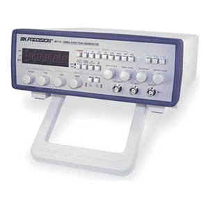
A function generator is capable of producing various waveforms (sinusoidal, square, triangle, sawtooth, etc.) over a wide range of amplitudes and frequencies. Knowing how to quickly adjust the generator to achieve a desired output will save you a considerable amount of time. You can find a function generator in the cabinet to the left of the tool crib window. Note that in order to use knobs other than frequency on the older function generators, you must pull the knob towards you. Please return it to the cabinet when you finish using it!
1.4.1 - Set up the function generator to produce a triangle waveform with a frequency of approximately 1 kHz and an amplitude near the middle of it�s range.
1.4.2 - There should be a BNC-alligator cable already attached to the output of the function generator (not to TTL/CMOS or VCG). Connect the oscilloscope probe to the alligator clips. Describe what you see on the scope.
1.4.3 - To help visualize periodic signals, the oscilloscope has a triggering function. Press the TRIG MENU button on the oscilloscope. Set the Type to Edge, the Source to CH 1, the Slope to Rising, the Mode to Auto, and the Coupling to DC (most, if not all, of these are likely set already). You should see small arrows on the top and right side of the scope trace. Describe what happens when you turn the LEVEL knob. What happens when you move the trigger level (the right arrow) beyond the extents of the signal?
1.4.4 - Play with the various knobs and settings on the function generator, and watch the output on the oscilloscope. In particular, describe the interplay between the DC offset and the amplitude settings.
2: PASSIVE FILTERS
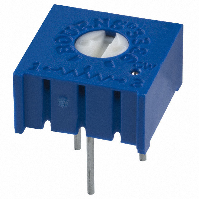
2.1 - Potentiometers
Grab a potentiometer (1k or greater) from the mini-store, and a pair of alligator wires from the back of the lab.
Using a multimeter, measure the resistance between the various pairs of leads, and make sure that you understand how the three pins of the physical device correspond to the potentiometers in the schematics of Part 1 below. Continued to watch the multimeter as you turn the knob on the potentiometer, and make sure you understand how it works.
Connect one end of the potentiometer to the (+) terminal of the fixed 5V output from the power supply, connect the other end of the potentiometer to (-) terminal of the fixed 5V supply, and connect the multimeter between the (-) end of the potentiometer and the wiper (middle pin). Turn on the power supply and observe the voltage on the multimeter. Describe the mathematical relationship between the knob angle and the output voltage.
When you're done, please return the potentiometer to the correct bin in the mini store.
2.2 - The RC Filter
There will be numerous times when you may want to remove either the high or low-frequency component from a signal. Though there are some limitations, one of the easiest ways to do this is with a passive filter built from a resistor and a capacitor.
2.2.1 - Set the function generator to create a sinusoidal signal with a frequency equal to 1000 times the day of the month on which you were born and with a peak-to-peak amplitude of 8.0V, centered about 5.0V. You should use the measurement tools on the scope (mean, pk-pk, freq, etc.) to get this as close as possible. (Note - as you should have discovered above, the peak-to-peak amplitude and DC offset of the function generator are not independent. Yes, we know that this is annoying.)
2.2.2 - Design and implement a passive RC filter to remove the DC component from your signal with a minimum of distortion to the high-frequency component of the signal (in other words, your output should be very close to an 8.0V sinusoid, centered at 0V). You can use discrete resistors or a potentiometer for this, but make sure that you keep at least 1000 Ohms of resistance to prevent excessive current draw. Also, please use only ceramic capacitors to avoid polarity issues. What resistance and capacitance did you find to be most effective? What is the theoretical cutoff frequency (in Hz)? What are the mean and peak-to-peak voltages of your output signal?
2.2.3 - Redesign your filter circuit to remove only the high-frequency component of the signal (in other words, your output should be very close to a flat 5V). Again, keep the resistance over 1000 Ohms. What resistance and capacitance did you use? What is the theoretical cutoff frequency (in Hz)? What are the mean and peak-to-peak voltages of your output signal? Adjust the frequency coming from the function generator, while ensuring that the peak-to-peak and DC component of the signal remain unchanged (you can connect a second probe to CH 2 of the oscilloscope for this), and observe the output from the filter. Find the input frequencies that give peak-to-peak amplitudes of 0.5V, 1V, 2V, and 5V.
2.2.4 (required for 510, e.c. for 410) - To visualize the complex behavior of dynamic systems, we often turn to graphical tools. One of these is the Bode plot. Using Matlab (or some other graphing software), create a log-log plot of the frequency versus the dB magnitude (0 dB corresponds to no change in peak-to-peak amplitude through the filter) of the results from 2.2.3, along with as many more data points as you deem necessary to fill in the graph. Overlay your results with the theoretical response for the filter based on the nominal R and C values. Also mark the theoretical and measured cutoff frequencies. Include your plot in your submission. Discuss the agreement between the theory of operation and your experimental data.
3: CLEANUP & PARTING THOUGHTS
3.1 - Cleanup
Please return the DMM and function generator to the cabinet, and clean up your work area.
3.2 - Parting Thoughts
You've decided to start coaching a high-school robotics team (good for you!). They have been struggling with high-frequency noise on one of their sensor lines, but they don't know how to get rid of it. Recognizing that they don't understand much beyond Ohm's law, lay out a clear, concise derivation and explanation for passive low-pass RC filters, beginning from the fundamental relationships for a resistor and a capacitor. If you use information from anywhere beyond your own head, please provide appropriate citations.